 Curious Patents
Tesla's Turbine with No Blades
In 1911 Nikola Tesla showed off an engine with no blades: a stack of smooth, flat disks on a shaft, turned by the way steam clings to metal. It never went on sale. The same drag, with one rule turned round, ended up in a speedometer on the dashboards of Packards and Rolls-Royces. Run the turbine and watch the steam spiral through it, spin the speed indicator, and read the patents and every source.
Watch the episode
Disks, not blades
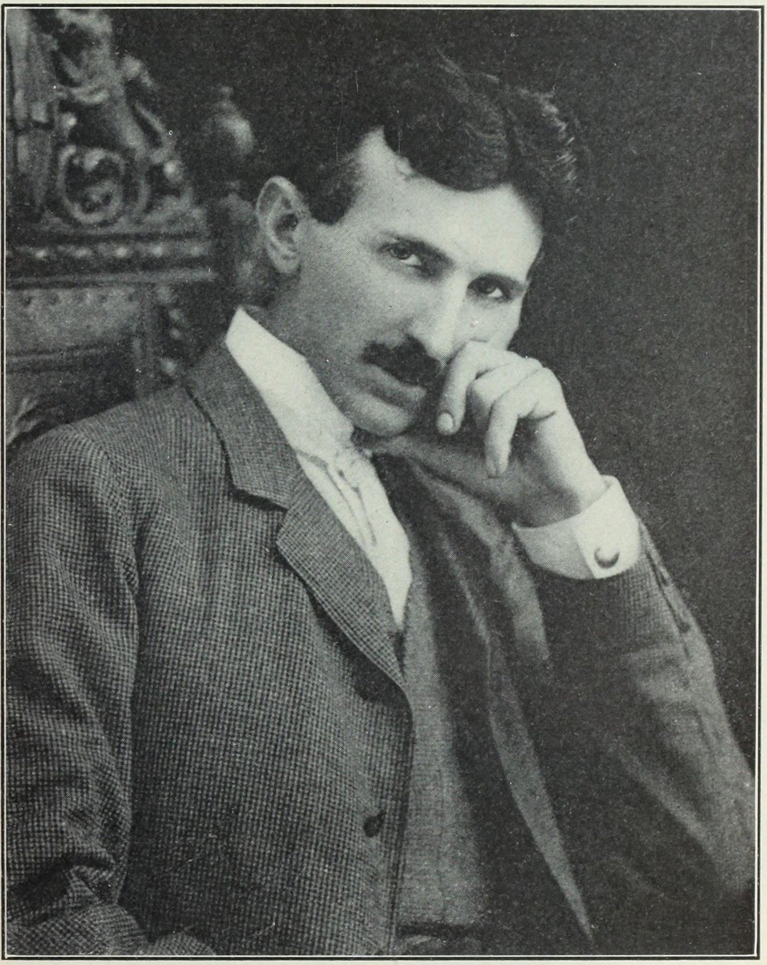
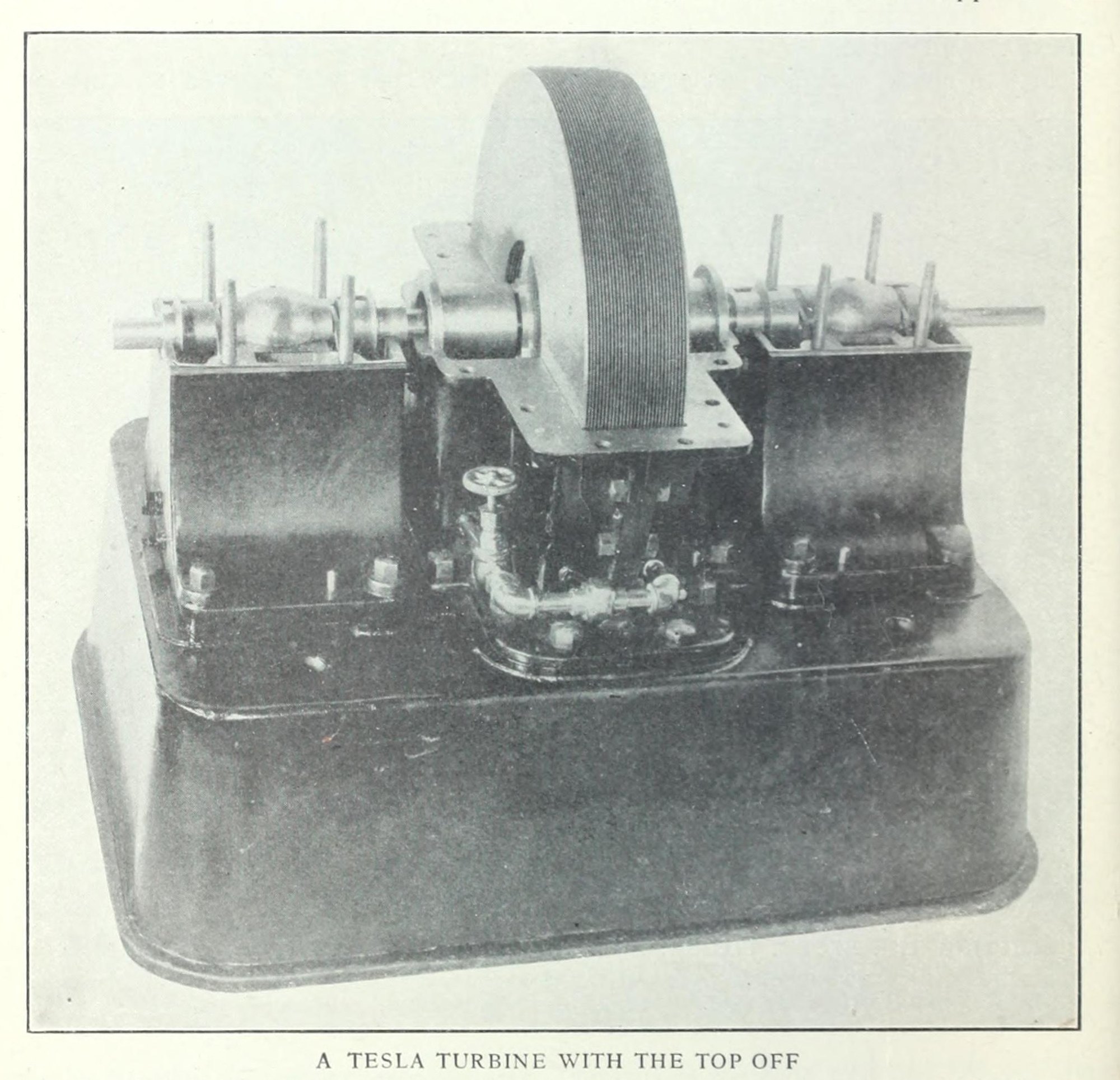
By 1911 the big power stations ran on steam turbines with blades: jets of steam striking rows of curved blades on a wheel. Tesla's turbine patent throws the blades away. Its runner is "a plurality of flat rigid disks" on a shaft, held a small distance apart, with nothing else for the steam to push against.
What turns it, the patent says, are two properties every fluid has: "adhesion and viscosity". Steam entering at the rim clings to the faces of the disks and drags on itself, and so it drags the disks round. Tesla did not claim to have discovered the effect. It is "of daily observation", he wrote, "but I believe that I am the first to apply them in a practical and economical manner".
On 12 September 1911 The Sun of New York printed an interview with him at the Waldorf-Astoria. The engine had no "buckets, vanes or sliding contacts", he said, and the same principle "will give the world a flying machine unlike anything that has ever been suggested before. It will have no planes, no screw propellers".
Two patents came out of it, granted on the same day, 6 May 1913. The first, applied for on 21 October 1909, is a pump, Fluid Propulsion (US 1,061,142). The second is the turbine (US 1,061,206), applied for on 17 January 1911 and split off from the pump's application.
A pump run backwards
The pump came first. Turn the disks of 1,061,142 with a motor and they drag the fluid round with them. Flung outward, it travels in a spiral from the openings near the centre to the outlet at the rim, its path "continuously increasing" as it goes.
Run it the other way and it is a motor. The turbine patent says so in as many words: "the operation is reversible, for if water or air under pressure be admitted to the opening constituting the outlet of a pump ... the runner is set in rotation". Steam goes in at the rim and spirals inward, giving up its speed to the disks, until it leaves through the openings next to the shaft.
The pump patent also imagines one disk machine driving another, through the fluid alone: "when transmitting power from one shaft to another by such machines, any desired ratio between the speeds of rotation may be obtained". That sentence comes back later in the story.
Run the turbine
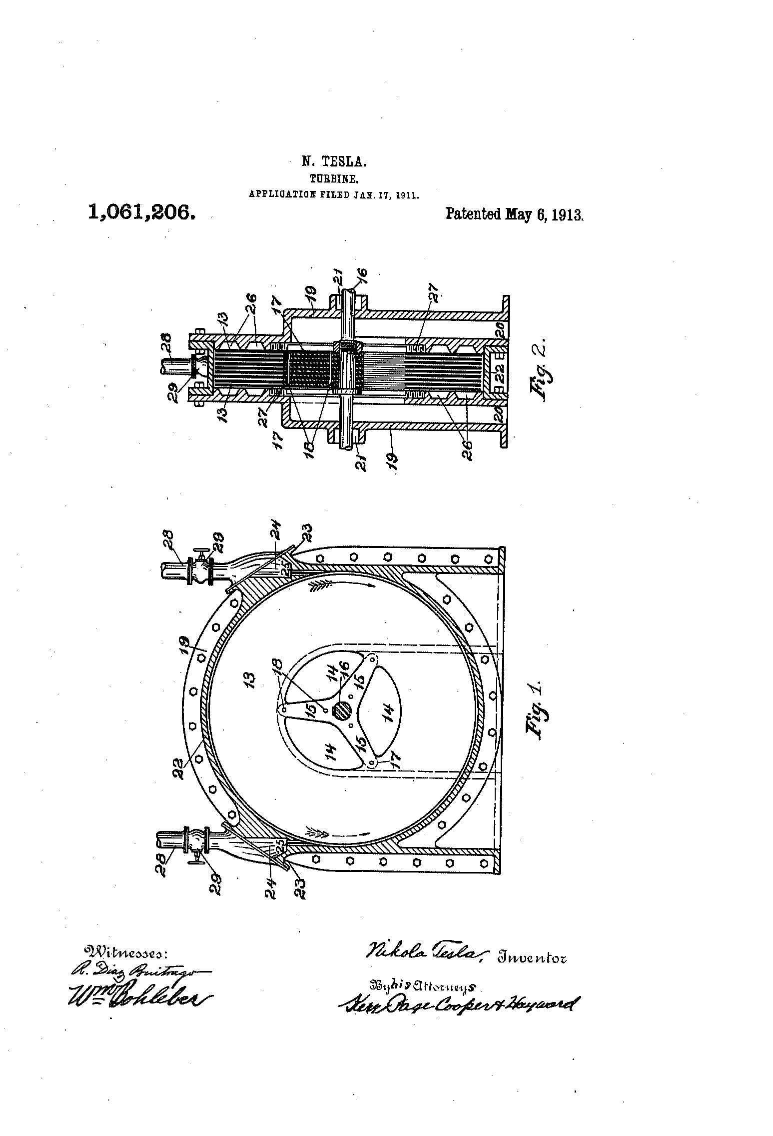
This is the episode's reconstruction of 1,061,206, drawn from Fig. 1 and Fig. 2 and stood upright. Steam comes in through one of the two nozzles 25, which enter the casing at a tangent to the rim. Which one you open decides the direction: the right-hand inlet as drawn turns the runner clockwise (the patent's solid arrow), the left-hand one counter-clockwise (its dotted arrow). The steam then follows "a spiral path and with continuously diminishing velocity until it reaches the orifices 14 and 20".
The patent says how that path changes with the work the machine is doing. With no load it is long, "consisting of many almost circular turns". Put a load on and the runner slows; then "the turns are reduced, and the path is shortened". Move the load slider and watch the red line. Its exact shape is ours: the patent states only the rule, and the line is computed from a simple drag model that follows it.
From the patent: flat disks 13 keyed to the shaft 16 and held apart by washers 17, each with openings 14 next to the shaft and spokes 15 between them; the ring 22, bored a little larger than the disks; the end castings 19 with the outlets 20 and stuffing boxes 21; the nozzles 25 entering at a tangent, the pipes 28 and valves 29; the two inlets, about 42° either side of the top as measured off Fig. 1, each driving the runner its own way. The patent says it draws "but a few disks, with comparatively wide intervening spaces" for clearness, and so does the model: eight, drawn thicker than Tesla's 1/32 inch so they show. Ours: every size (the patent gives none), the shapes of the castings, base and valves, the speeds, and the steam's path, which our drag model draws to the patent's rule. Left out: the grooves 26, the packing 27 and the bolts. Shown slowed down.
Waterside, 1911
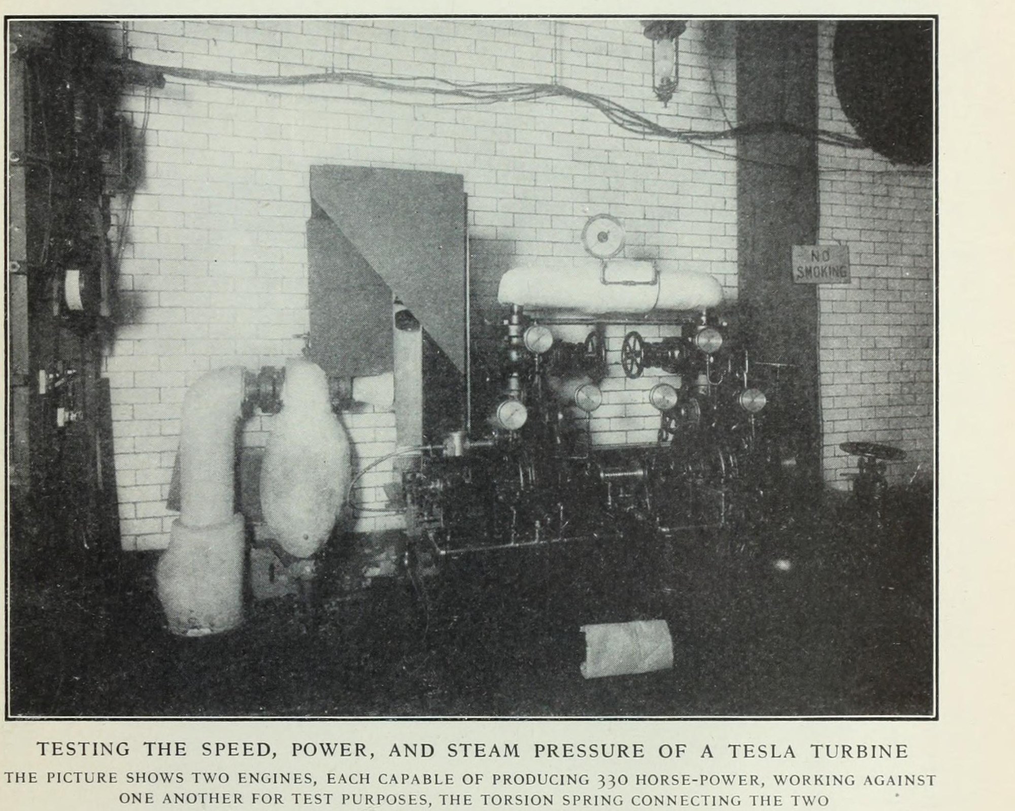
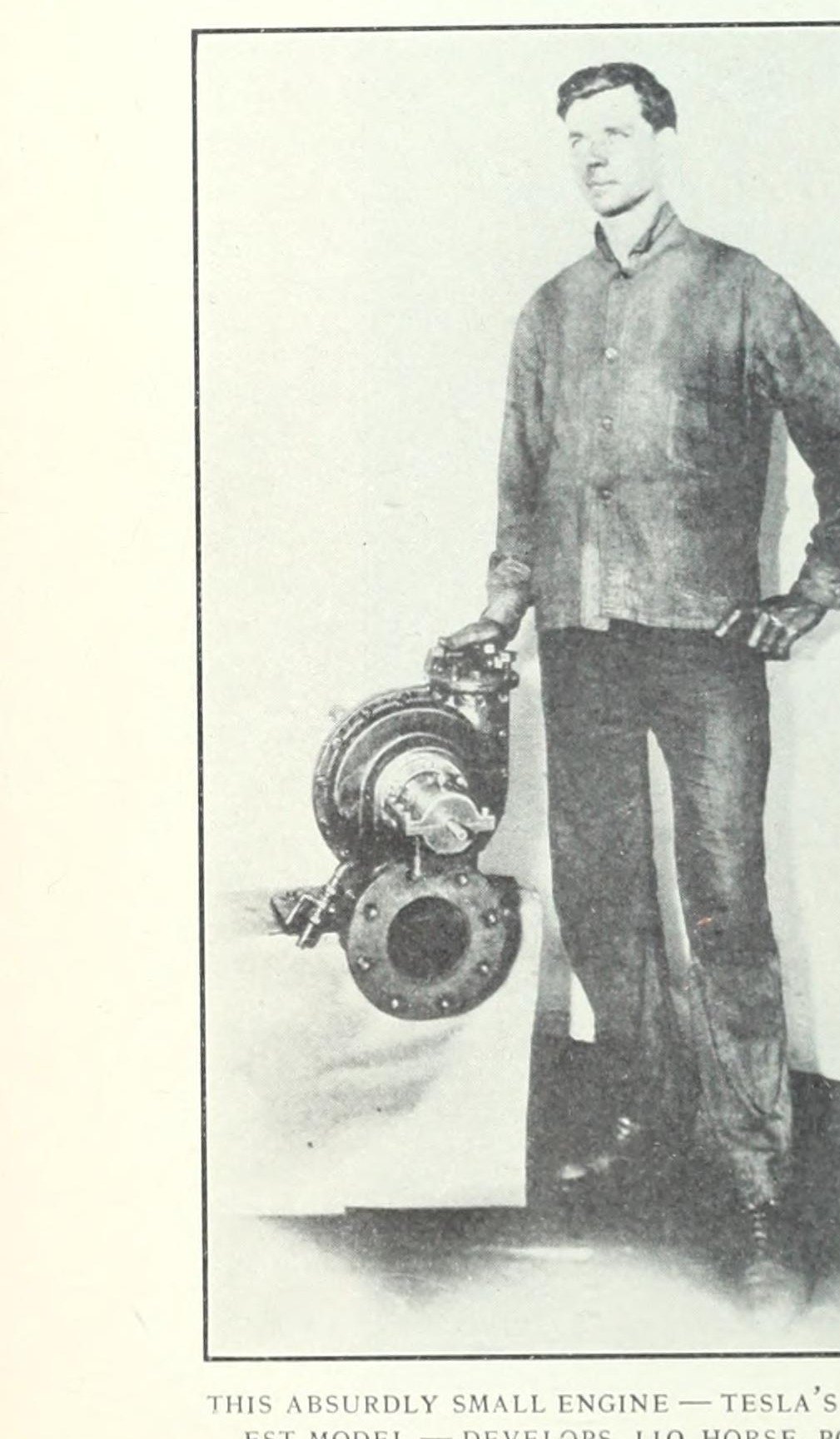
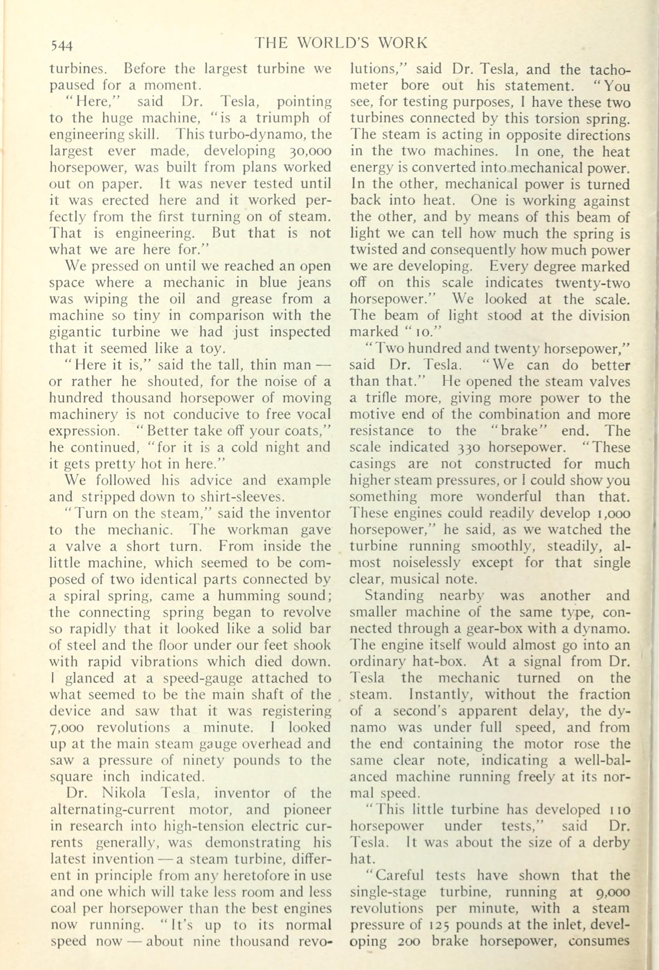
In 1911 Tesla tested a full-size machine at the Waterside power station of the New York Edison Company. A reporter, Frank Parker Stockbridge, followed him in one night for The World's Work. They walked past a turbine of thirty thousand horsepower to a machine so small that it "seemed like a toy".
There were two identical turbines, joined by a spring, with the steam driving them in opposite directions. "One is working against the other," Tesla told him. The harder they pushed, the more the spring twisted, and a beam of light showed how far: "Every degree marked off on this scale indicates twenty-two horsepower." The light stood at ten, 220 horsepower. "We can do better than that," Tesla said, opened the steam valves a little more, and the scale showed 330.
Scientific American, reporting the test in September 1911, gave two hundred brake horsepower at nine thousand revolutions a minute, from disks eighteen inches across. A smaller turbine was "about the size of a derby hat", and Tesla said it had given 110 horsepower under test.
Stockbridge's article ends on Tesla's hope of flying in a machine of his own one day, and his promise: "The Tesla turbine will be on the market long before that."
The numbers
At Waterside the turbine used thirty-eight pounds of steam an hour for every horsepower it delivered, with its exhaust going straight into the air (Scientific American, 1911). Our own calculation, from steam tables for the reported conditions, is that this turned about forty per cent of the steam's available energy into work. Tesla said it used only about a third of the heat it could, and that with more stages and a condenser it would need less than twelve pounds. That was a promise, not a measurement.
The best bladed turbines of the day, running with condensers, needed about ten pounds per horsepower-hour (the Encyclopaedia Britannica of 1911 gives about thirteen pounds per kilowatt-hour for the large sets). That is not a fair race, since Tesla's machine had no condenser, but it shows the gap he had to close.
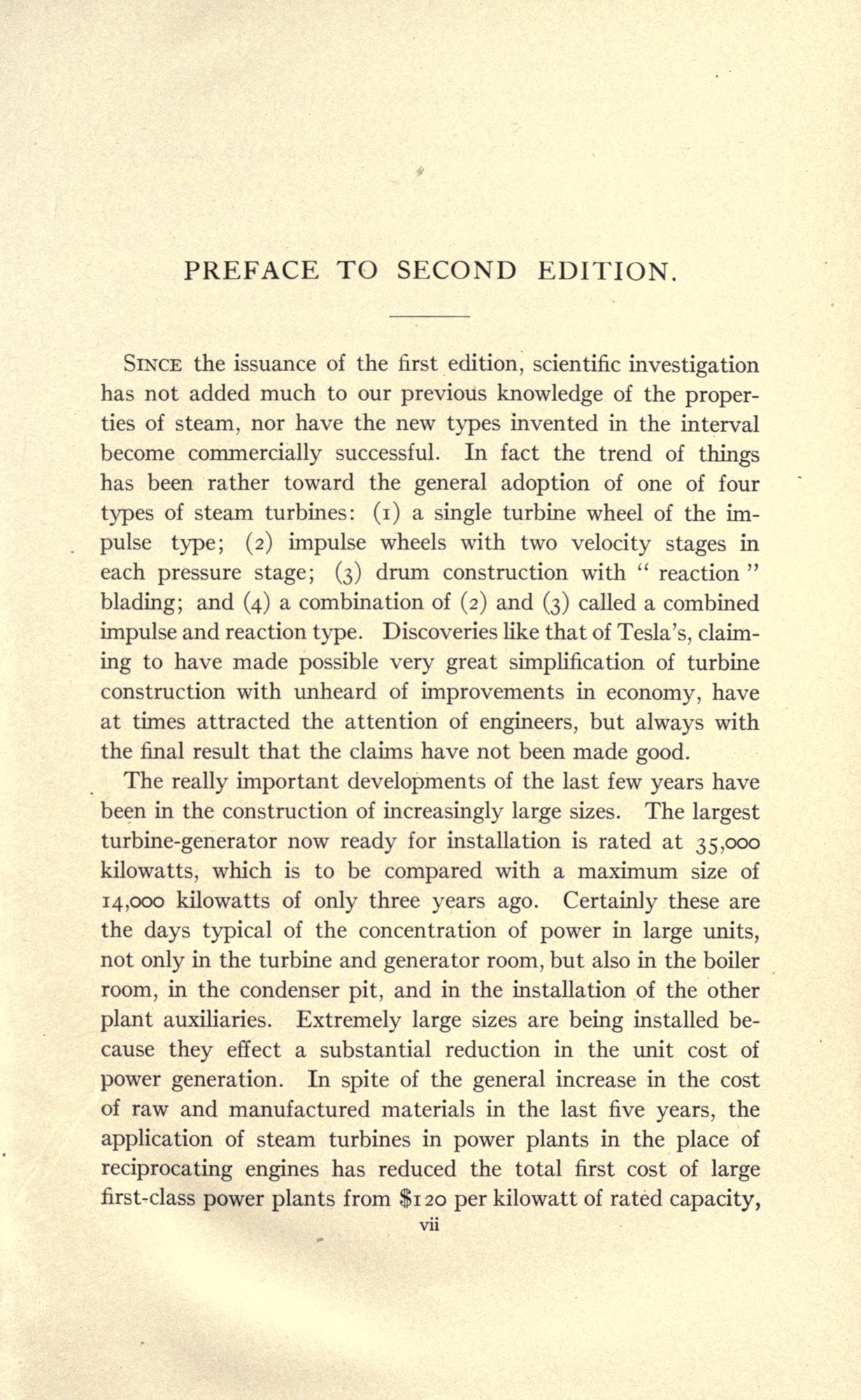
In 1914 a standard textbook summed up the engineers' view. Discoveries like Tesla's, wrote James Ambrose Moyer, "have at times attracted the attention of engineers, but always with the final result that the claims have not been made good."
Later, the Allis-Chalmers company of Milwaukee built three Tesla turbines, the largest with fifteen disks five feet across. Our only account is the one in John J. O'Neill's biography of Tesla (1944), which quotes the company's engineer, Hans Dahlstrand: a maximum mechanical efficiency of "approximately 38 per cent", manufacturing costs that "could not compete", and disks that, when the big unit was taken apart, "had distorted to a great extent". O'Neill gives no date for the tests, and we have not found the report itself.
Speed was the enemy. The stress in a spinning disk grows with the square of the speed at its rim, and these were thin plates. Years later O'Neill asked Tesla why he had stopped working with Allis-Chalmers. "They would not build the turbines as I wished." O'Neill wrote that he would say no more.
The same drag, turned round
By 1916 Tesla was broke. On 17 March The Evening World reported that a New York court had examined him over unpaid taxes. "How do you live, Mr. Tesla?" "Mostly on credit. I have a bill at the Waldorf-Astoria that I have not paid for several years." (We have read this in the Library of Congress's machine reading of the page; the page image is still to be checked.)
Two weeks later, The Automobile of 30 March 1916 reported that the Waltham Watch Company had a new speedometer in production, with "a principle new in speed measuring". Tesla had applied for a speed indicator in May 1914. When it was granted, on 19 December 1916, its heading read "Nikola Tesla, of New York, N. Y., assignor to Waltham Watch Company". He had sold the patent to them.
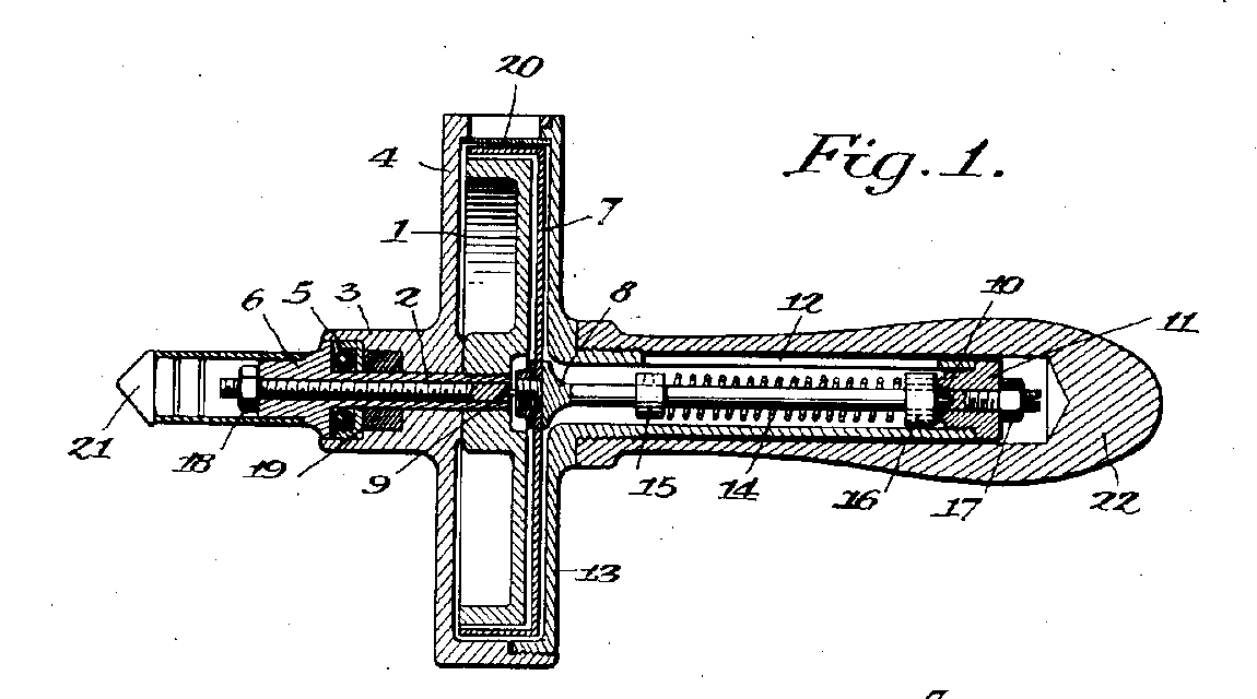
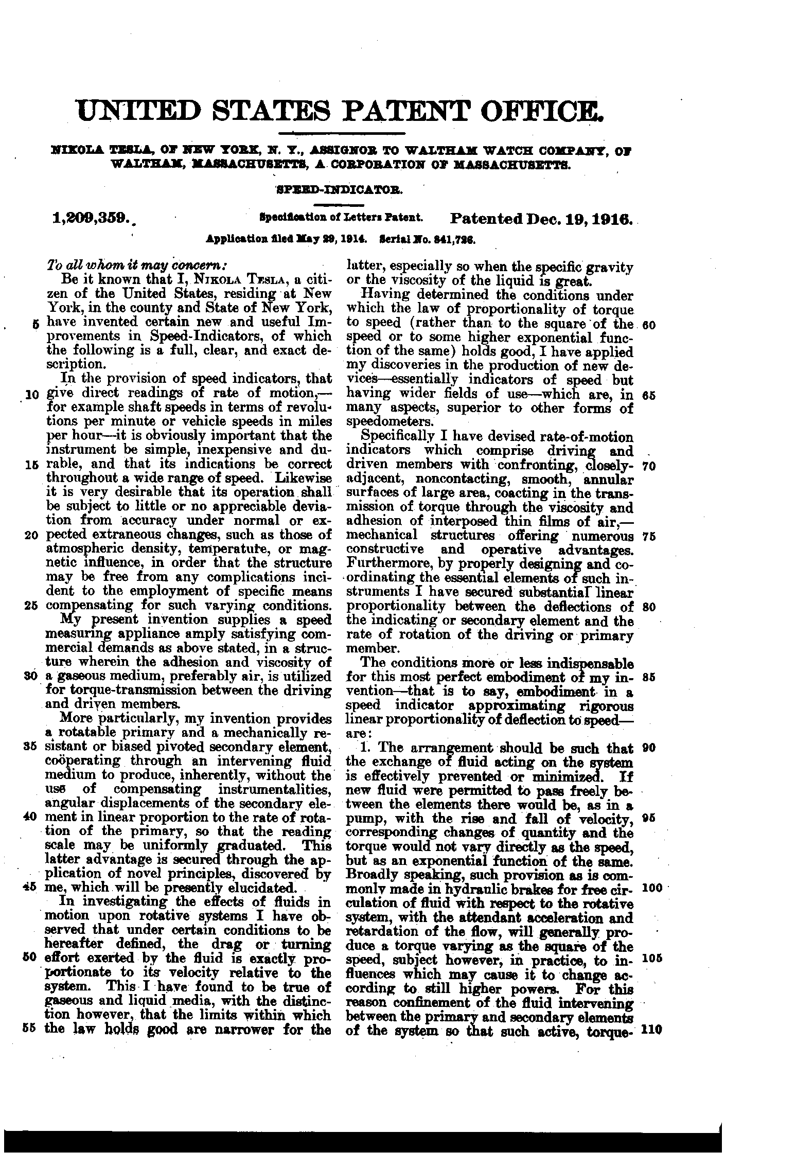
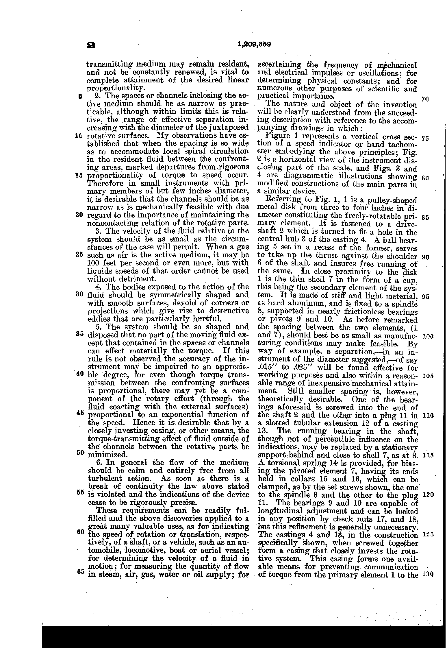
It runs on the turbine's drag: in Tesla's words, on "the viscosity and adhesion of interposed thin films of air". A disk 1 on the drive shaft spins inside a light aluminium cup 7, very close to it but never touching: for a disk three or four inches across, the patent gives a gap of fifteen to twenty-five thousandths of an inch. The air between them is dragged round, and drags the cup with it, until a coiled spring 14 holds it. The cup carries the scale, read under the index 23, and the faster the disk turns, the further the cup goes.
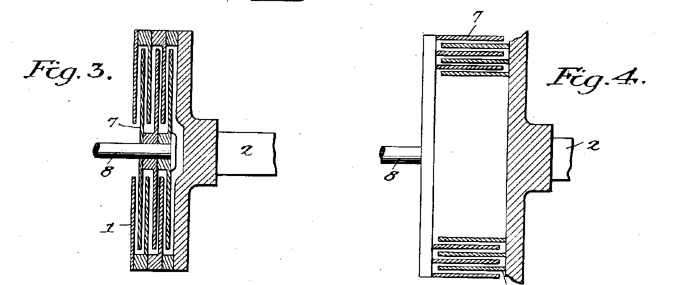
One rule is turned round. In the turbine the steam has to spiral through and escape. In the speed indicator the air must stay put: the particles, Tesla wrote, "should move in circles and not in spirals". That matters. If the air flows through, the pull grows with the square of the speed; keep it in, and the pull grows in step with the speed, so the scale "may be uniformly graduated", with no correcting gears. Tesla drew it two more ways, with interleaved disks and with interleaved cylinders (Figs. 3 and 4).
And there is the sentence from the pump patent of 1913: one disk machine "transmitting power from one shaft to another", through the fluid alone. Here it is, shrunk to fit behind a dial.
From the patent: the disk 1 on the drive shaft 2, the thin aluminium cup 7 round it on the spindle 8, the gap between them (here .020 inch on a 3½-inch disk, inside the patent's range), the torsion spring 14 between the collars 15 and 16, the window 20, the tip 21, the handle 22 and the index 23; the cup's turn in proportion to the speed. Ours: every other size, the shapes of the castings and handle, and the scale's range (0 to 3,000 r.p.m. over 270°). The cup follows a change of speed with a short lag, which is ours too. Drawing aids, also ours: the cut faces filled in, as in Fig. 1's section; the stripes inside the disk's rim; and the inset, which shows the scale from above with the casting left out. Left out: the check nuts 17, 18 and the seal 19.
On the dashboard
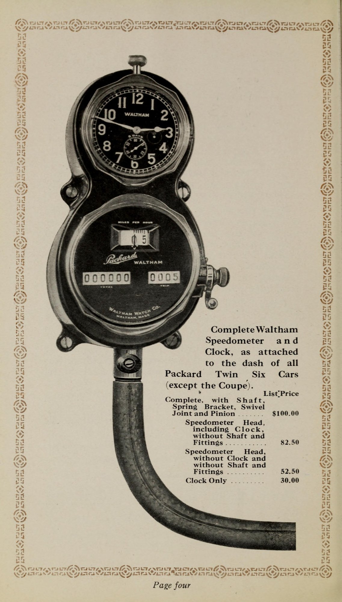
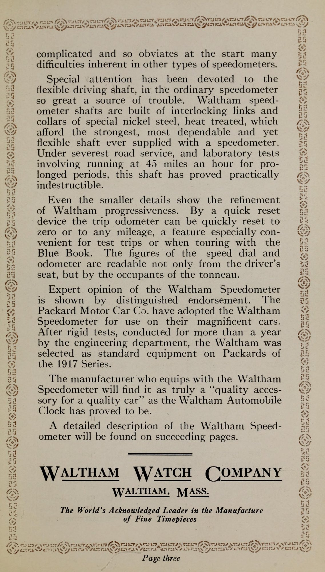
The Automobile reported that Waltham's first lot was twenty-five thousand. Waltham's 1916 catalogue says Packard tested the instrument "for more than a year" and made it standard on its 1917 cars.
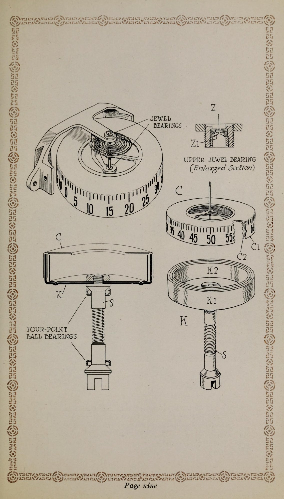
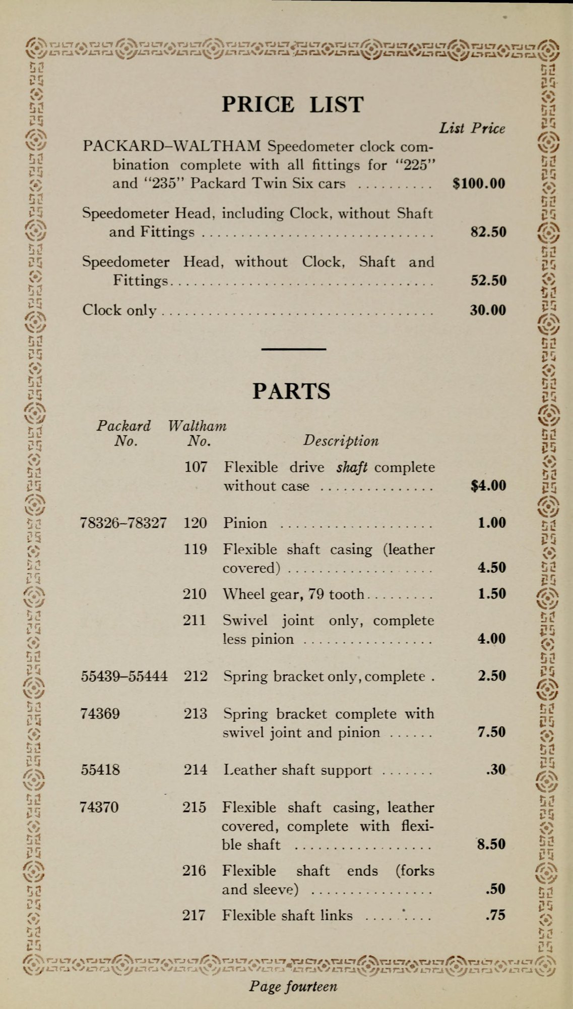
Inside, a spinning brass cup dragged on an aluminium cup eight thousandths of a centimetre thick, held back by a hairspring, like a watch. The head alone listed at $52.50 ≈ $1,600, and Waltham said heat, cold and altitude up to ten thousand feet did not affect it.
By 1921 its advertisements in the Evening Public Ledger of Philadelphia spoke of "the scientific air-friction principle, invented by Nikola Tesla", standard on Lincoln, Packard, Pierce-Arrow, Rolls-Royce and others. In 1926 the writer Kenneth Swezey told newspaper readers that in "the eighteen or twenty highest class motorcars", "you will meet an example of the versatile Tesla in the Waltham speedometer".
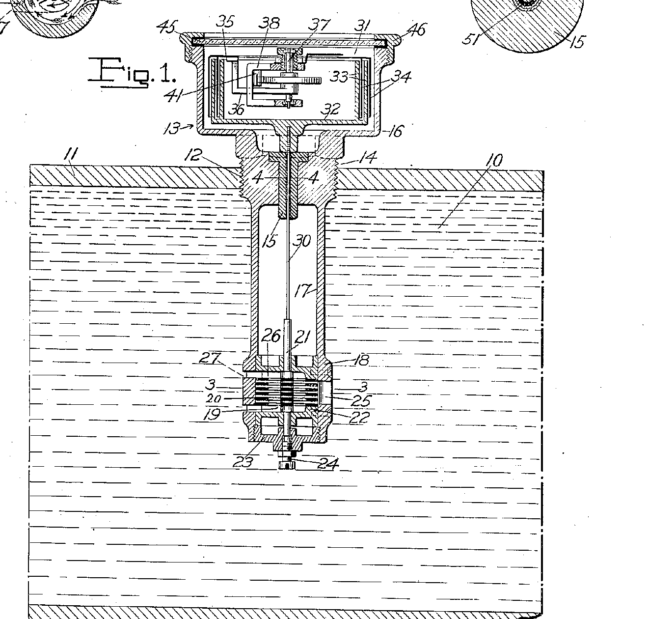
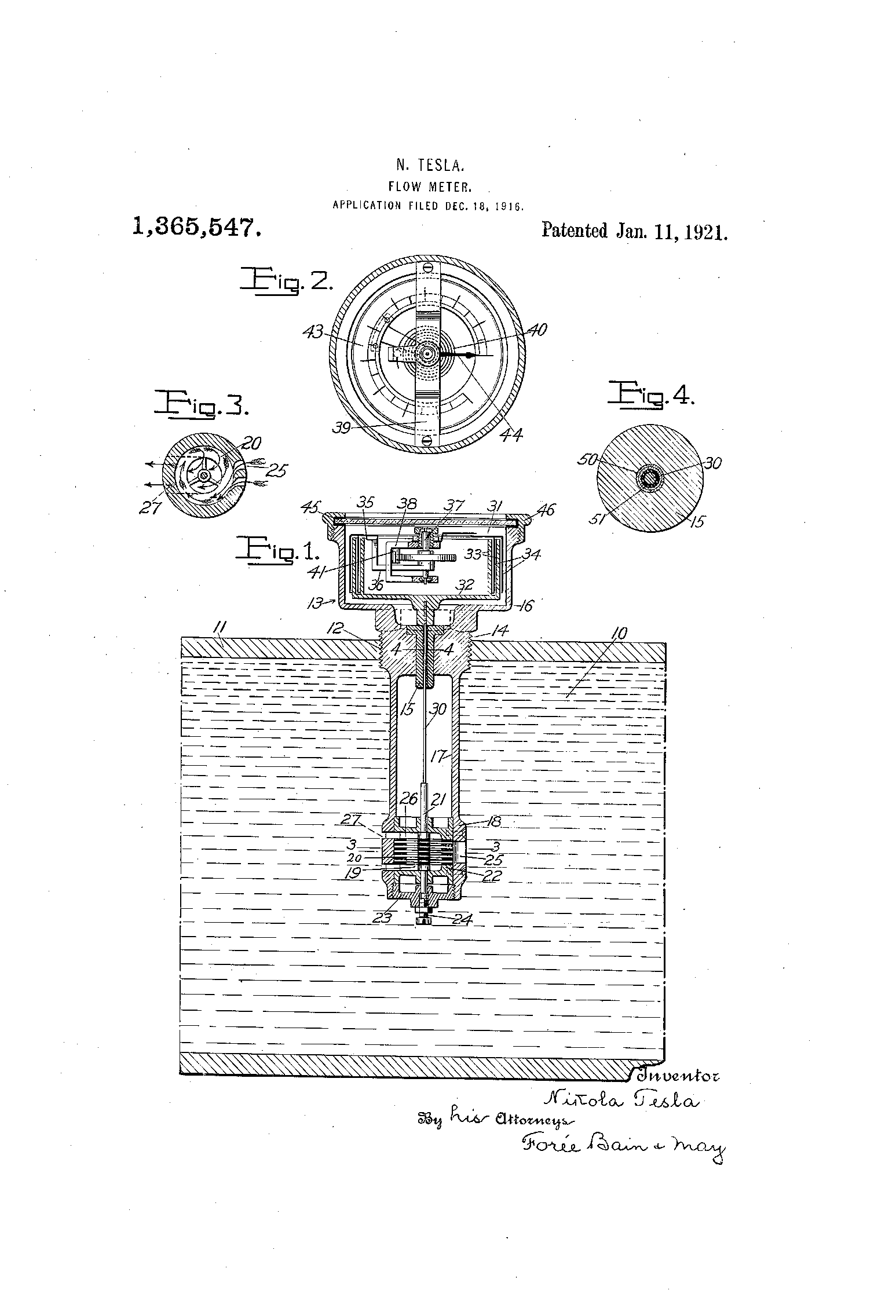
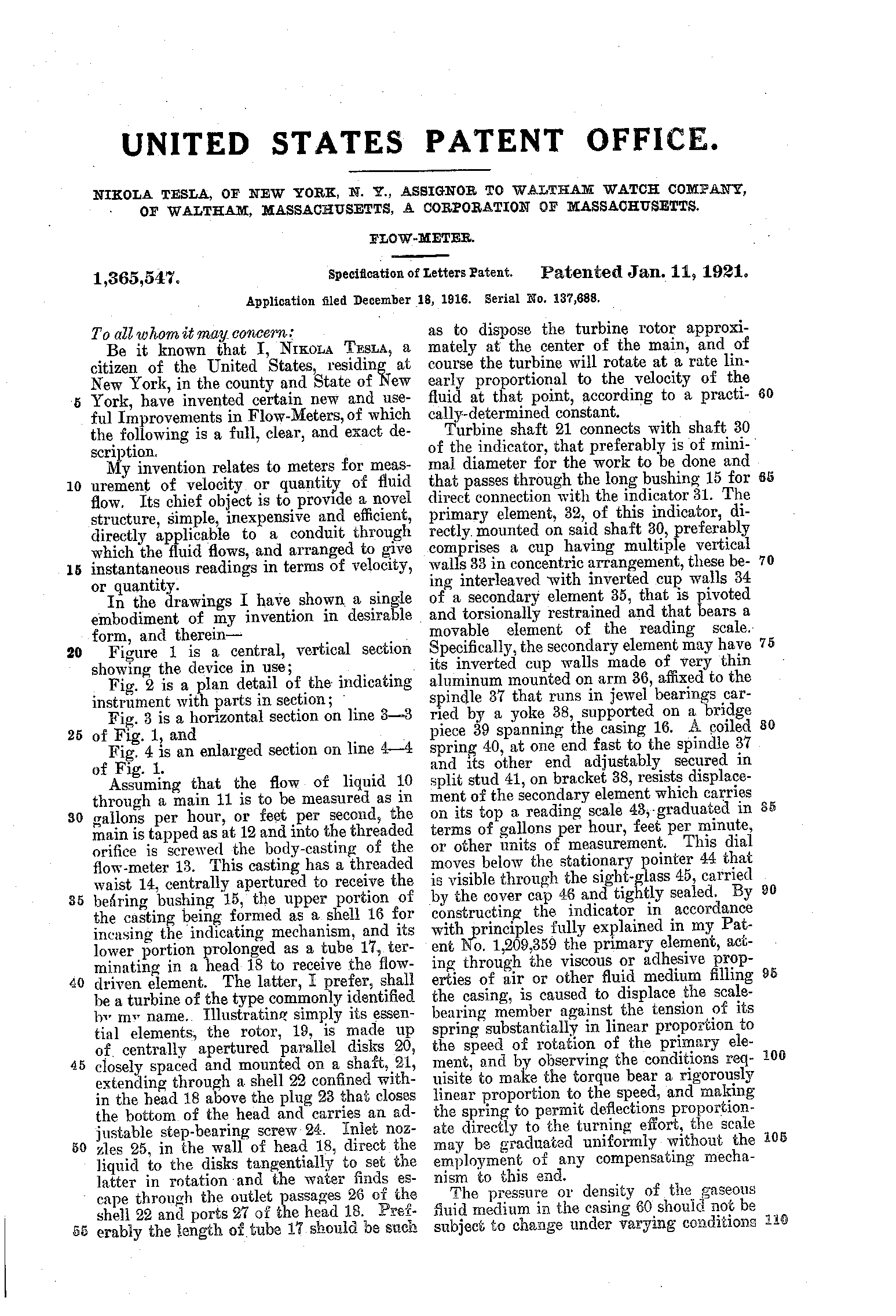
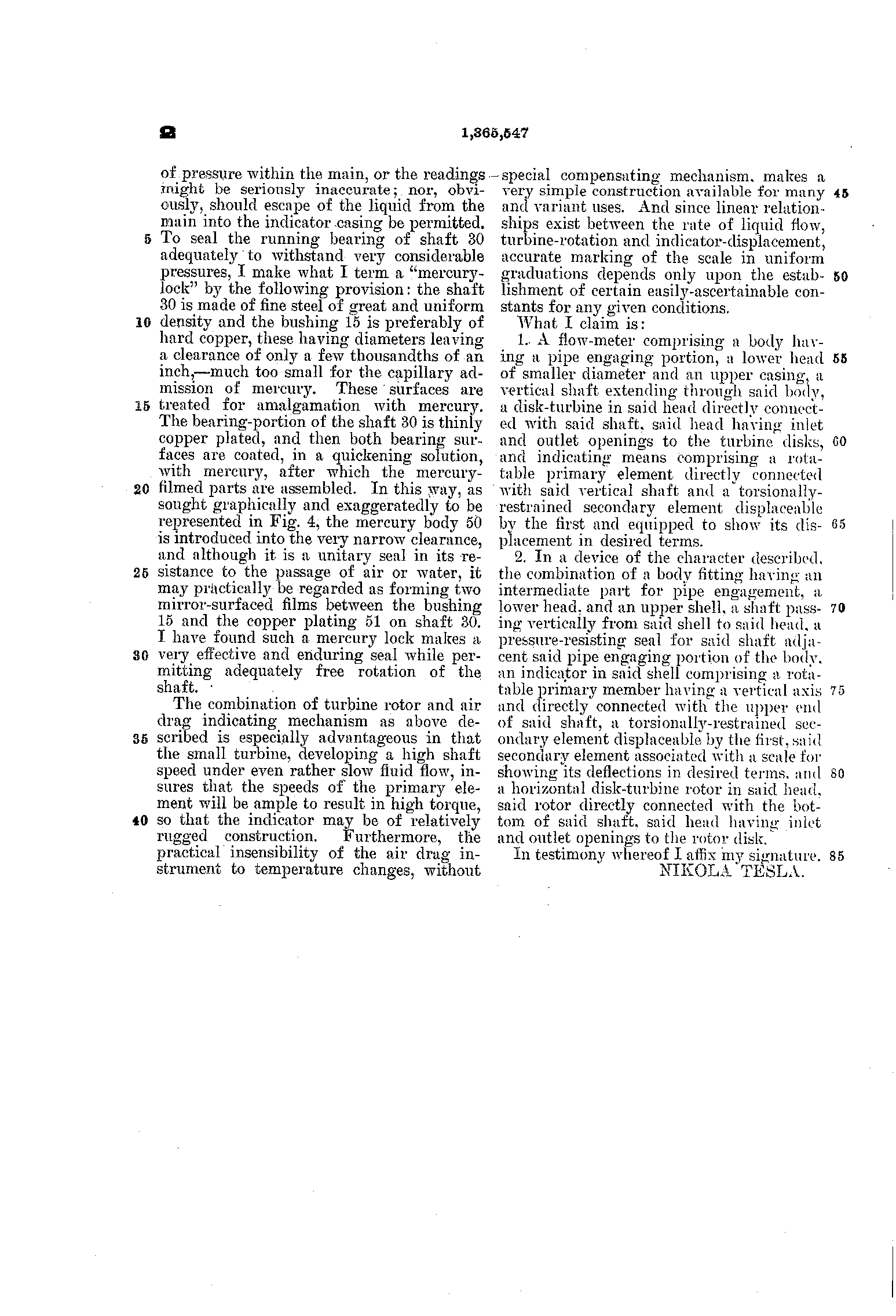
Tesla also sold Waltham a ship's log, a frequency meter and a flow meter, each reading its dial by air drag. The flow meter, US 1,365,547 (1921), puts both machines in one drawing: water drives "a turbine of the type commonly identified by my name", and its shaft turns an air-drag dial on top.
The other inventor, and the royalty
Tesla was not the first to patent an air-drag speedometer. Stead A. Asquith, of Waterloo, Iowa, applied for one on 5 December 1913, and it was granted as US 1,093,166 on 14 April 1914. His disks, the patent says, "pull with them, by adhesion, the air molecules", and drag a drum round against a spring. Tesla applied nearly six months later, six weeks after Asquith's patent had been granted.
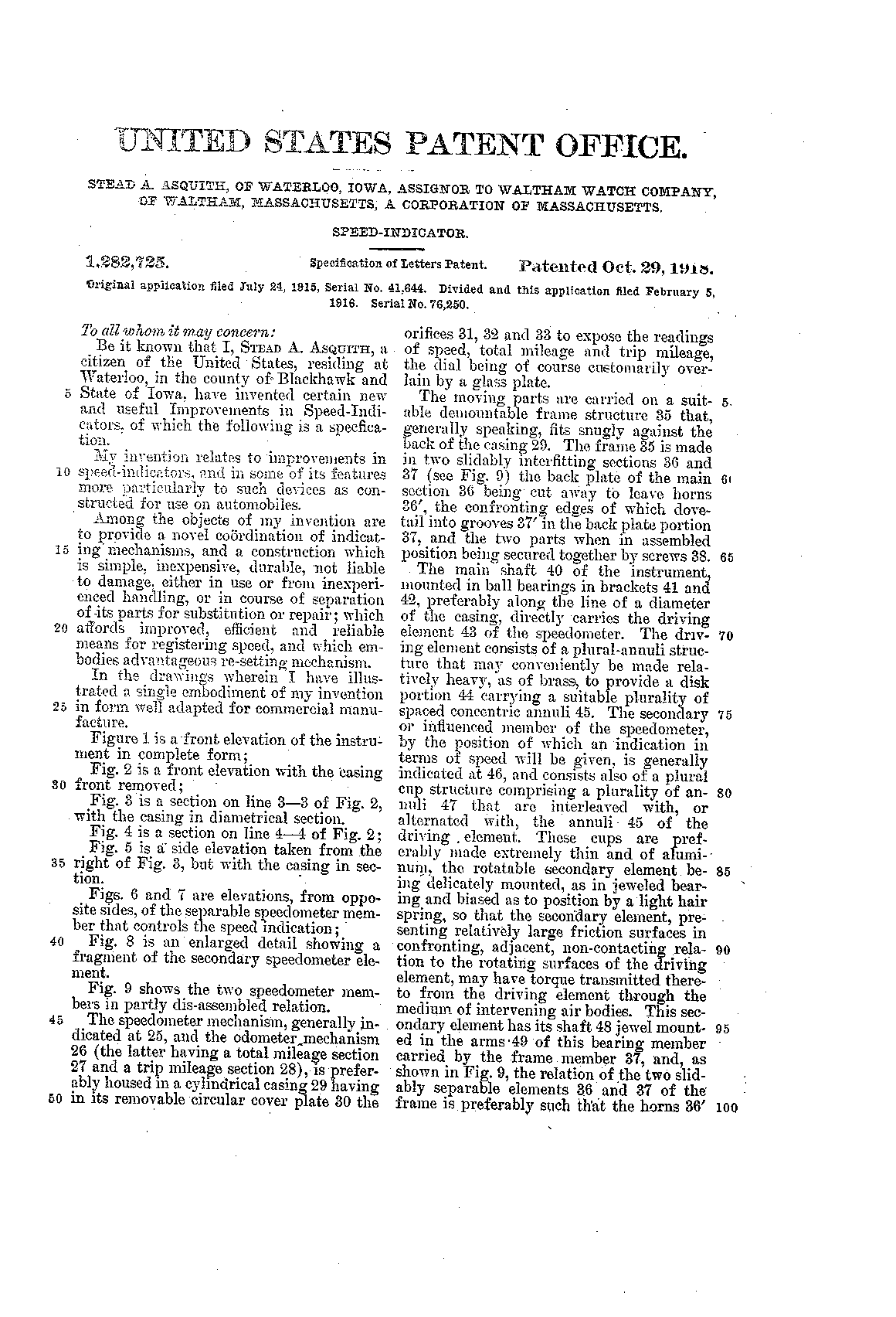
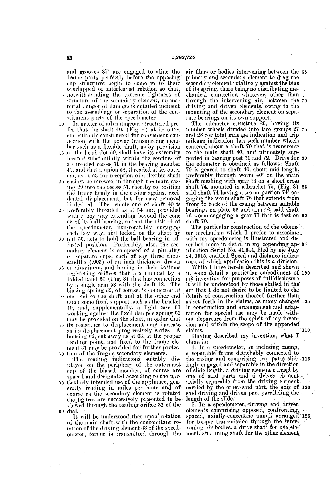
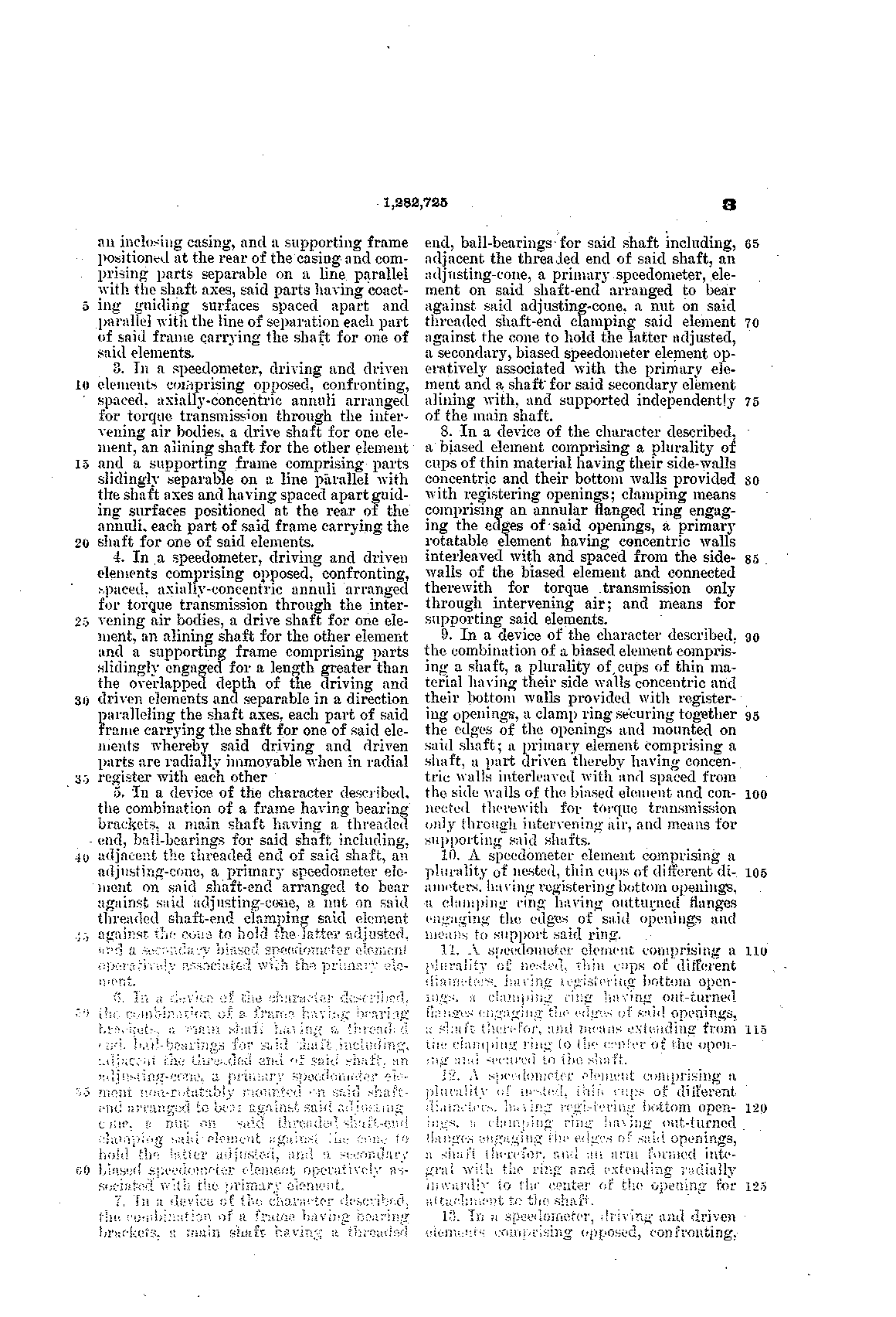
Waltham took a later Asquith patent too: US 1,282,725, granted in 1918, is headed "assignor to Waltham Watch Company". The company owned patents from both men. Its advertising named only Tesla. Who influenced whom, if anyone, the record does not say.

What Tesla got was a royalty on every instrument, reported as twenty cents ≈ $3.80. In the late 1920s Waltham wanted the rate cut. According to the Waltham Times (2026), letters now shown at the Charles River Museum in Waltham have Tesla arguing to keep it, and sending pages of praise from famous people to show that his name "added prestige". We have not seen the letters.
In 1929, by his grandnephew William Terbo's account of a letter Tesla wrote that year, he had borrowed $15,000 ≈ $280,000 against the Waltham contract, and had offered to cut his royalty by a third for $75,000 ≈ $1.4 million. "That seemed a lot to them." The patent ran out in 1933, and Waltham did not renew the arrangement. How much it paid him in all, we could not find out.
The flying machine
The turbine had one more job in Tesla's mind. In 1912 he told Stockbridge he had gone into electricity to solve the problem of his life: "an engine sufficiently light and powerful to operate the ideal flying machine".
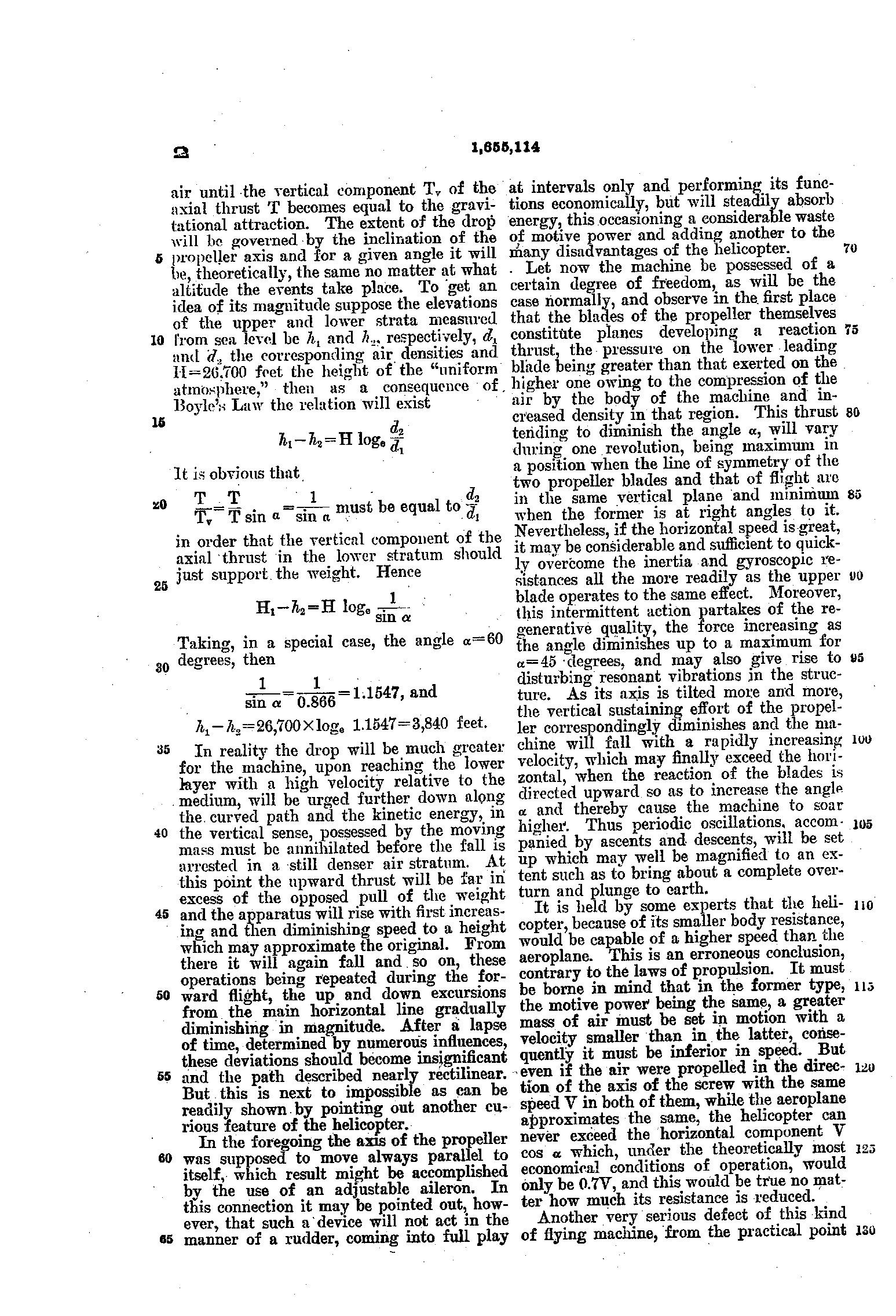
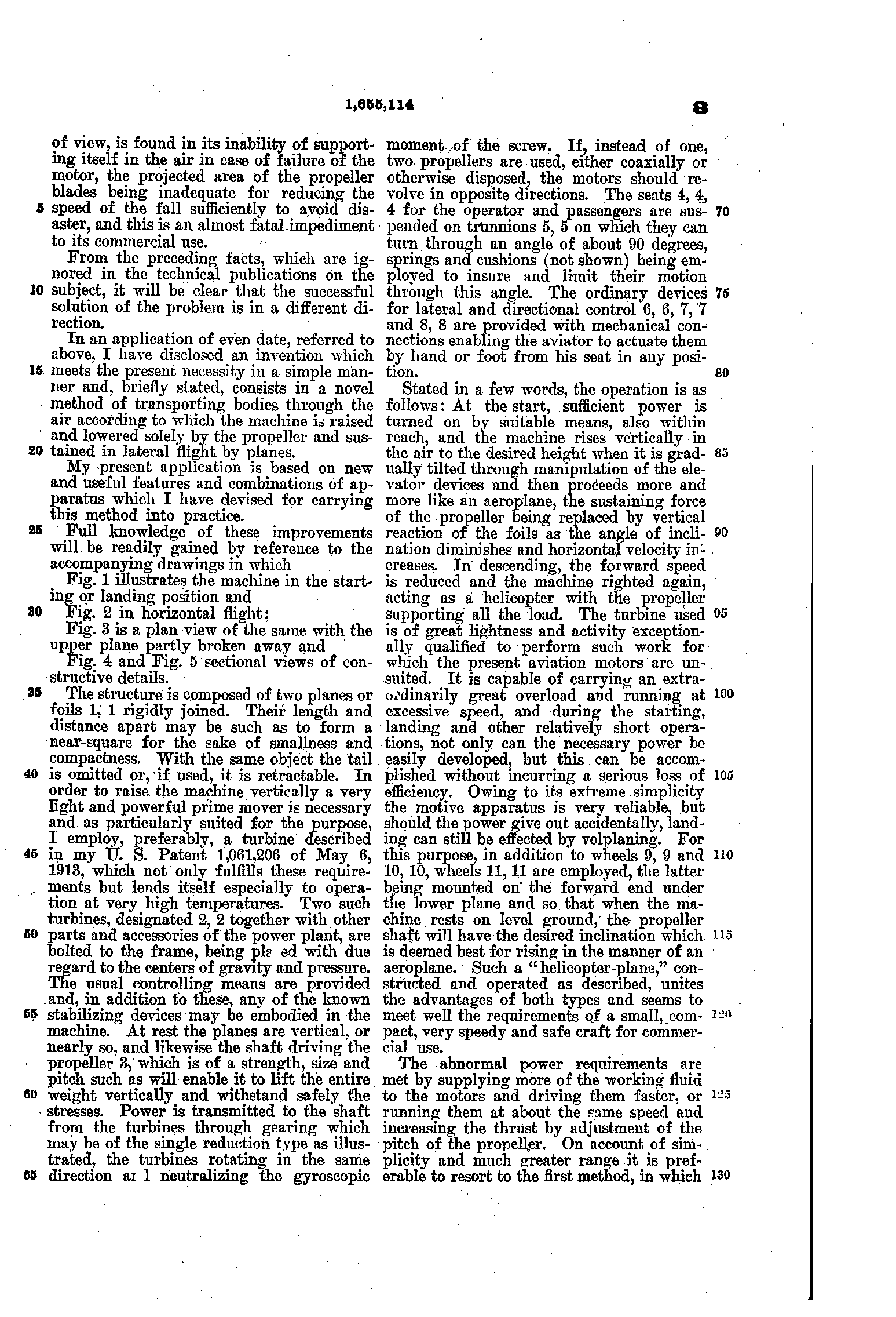
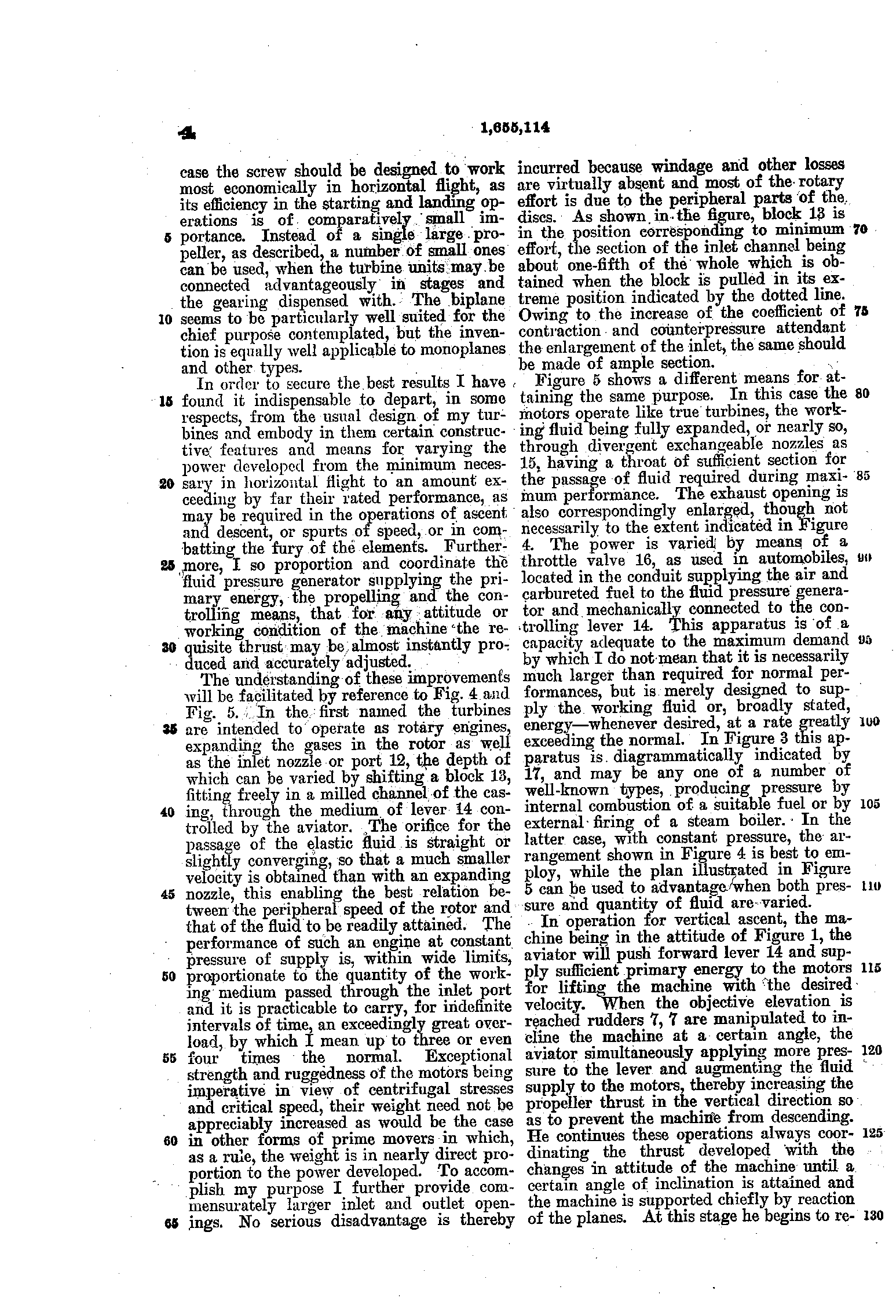
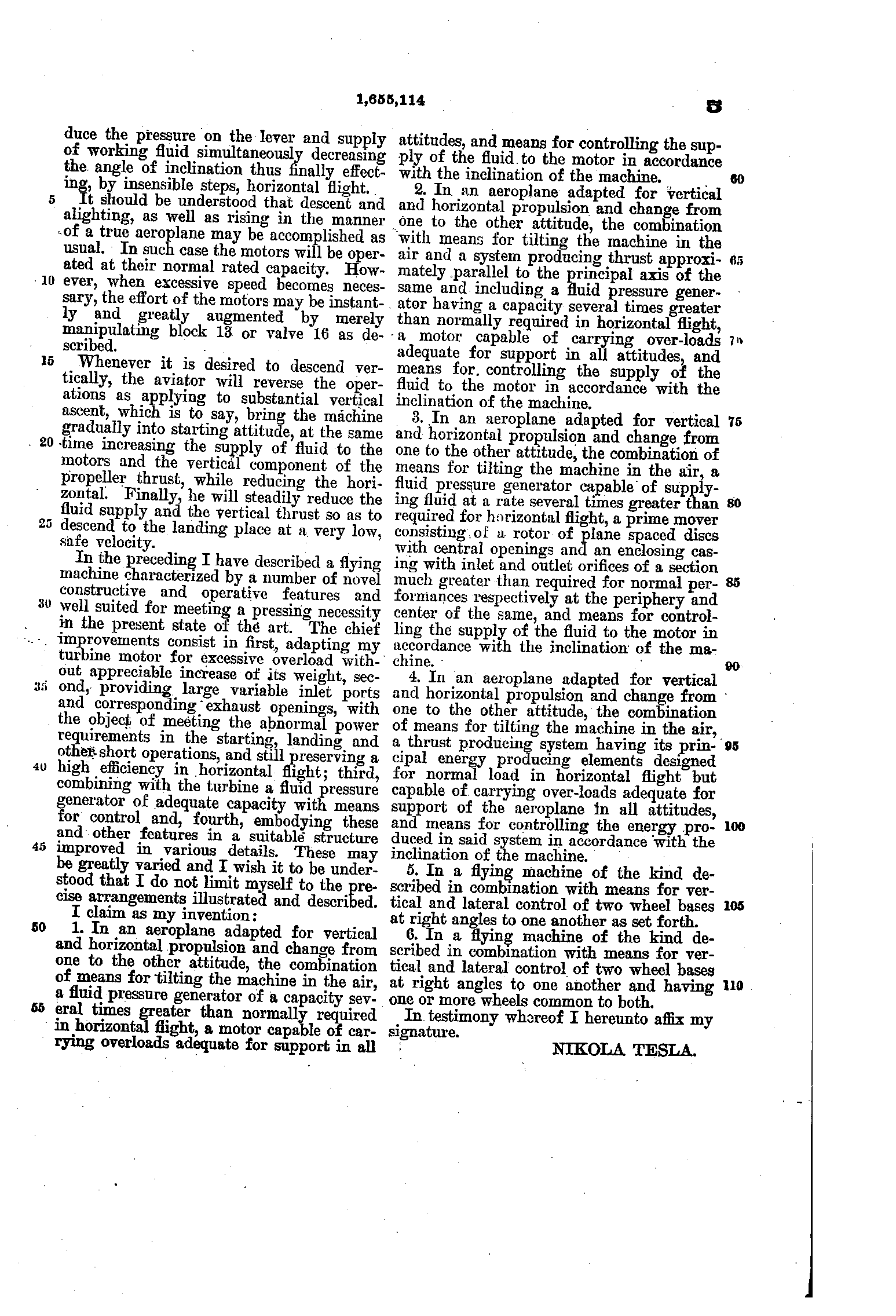
In January 1928, at seventy-one, he was granted US 1,655,114 for what he called a "helicopter-plane". Its engines were his disk turbine: "I employ, preferably, a turbine described in my U. S. Patent 1,061,206", two of them, geared to one propeller. On the ground it stands with its wings upright and its propeller pointing at the sky. The pilot opens the turbines' inlets with a lever, and it rises straight up. At height the controls tip it forward until the wings take the weight and it flies like an aeroplane, while the seats swing on pivots "through an angle of about 90 degrees" so the riders stay upright. For take-off, Tesla wrote, the turbines could carry an overload of "three or even four times the normal".
Play the take-off in the order the patent gives it, or drag the slider to any moment. Drag the picture to turn it; scroll or pinch to zoom. The inset is Fig. 4: one turbine cut open, where lever 14 slides block 13 to set the depth of the inlet port 12.
From the patent: the planes 1, "rigidly joined", upright at rest, "and likewise the shaft driving the propeller 3"; two turbines 2 of his US 1,061,206, geared to the propeller and "rotating in the same direction"; in each, the inlet port 12, whose depth is set by block 13 through lever 14, one-fifth open with the block in, as Fig. 4 draws it; the seats 4 on trunnions 5, which turn "through an angle of about 90 degrees"; the controls 6, 7 and 8, the wheels 9, 10 and 11, and the fluid pressure generator 17, a box in the drawings. The order of the take-off is the patent's. Ours: every size (read off Fig. 1), the gear ratio (3 : 1) and its teeth, the turbines' size and eight disks, the frame's members, the riders, the path, speeds and timing, and how far the rudders 7 turn. Each seat swings freely on its trunnion, damped, with stops at the ends of its range; nothing holds it level. Left out: the exhaust elbow and the linkages to the controls. The propeller and turbines are shown slowed down.
In 1911 he had promised a flier with "no planes, no screw propellers". This one had both. When the patents were announced, the New York Herald Tribune reported that no machine had yet been built under them (we have read the report only in a transcription). None ever was, as far as we can find.
What happened next
Engineers kept testing Tesla turbines for the rest of the century. In 1991 Warren Rice, whose review is the field's standard reference, gave the verdict: the disks themselves can be very efficient, but getting the steam into and out of them efficiently has proved very hard, and "only modest machine efficiencies have been demonstrated". A study published in 2022 found that computer simulations promise forty to sixty per cent, while real machines reach about twenty at best.
Where the idea has found work is as a pump, for thick or gritty liquids that would wear out blades. The engine with no blades never went on sale, and never flew. The same drag, held still in a cup of air, sat on the dashboards of some of the finest cars of the 1920s, and paid its inventor twenty cents a time.
Read the original patents
All seven patents are in the public domain. Click a page for full resolution; drawing sheets come first, then the specification.
US 1,061,206, Nikola Tesla, Turbine, filed 17 January 1911, granted 6 May 1913
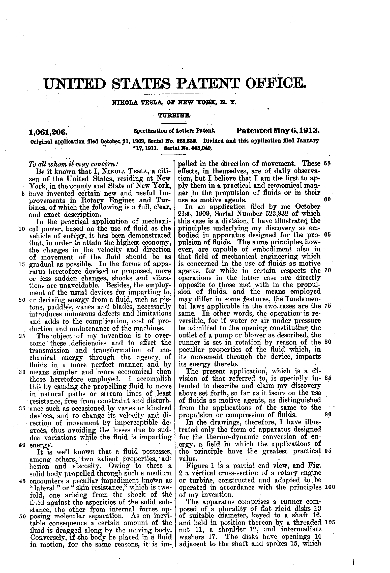
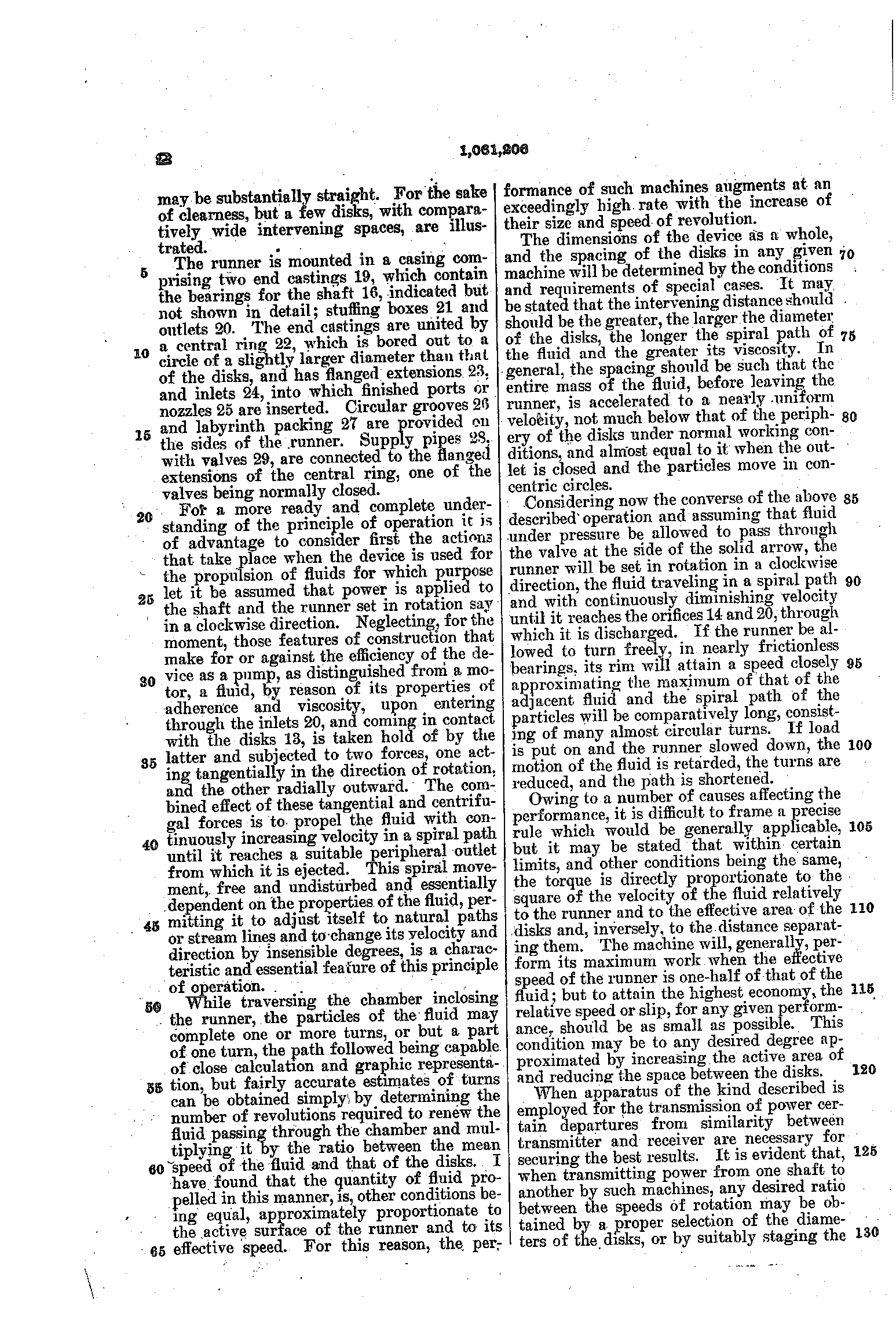
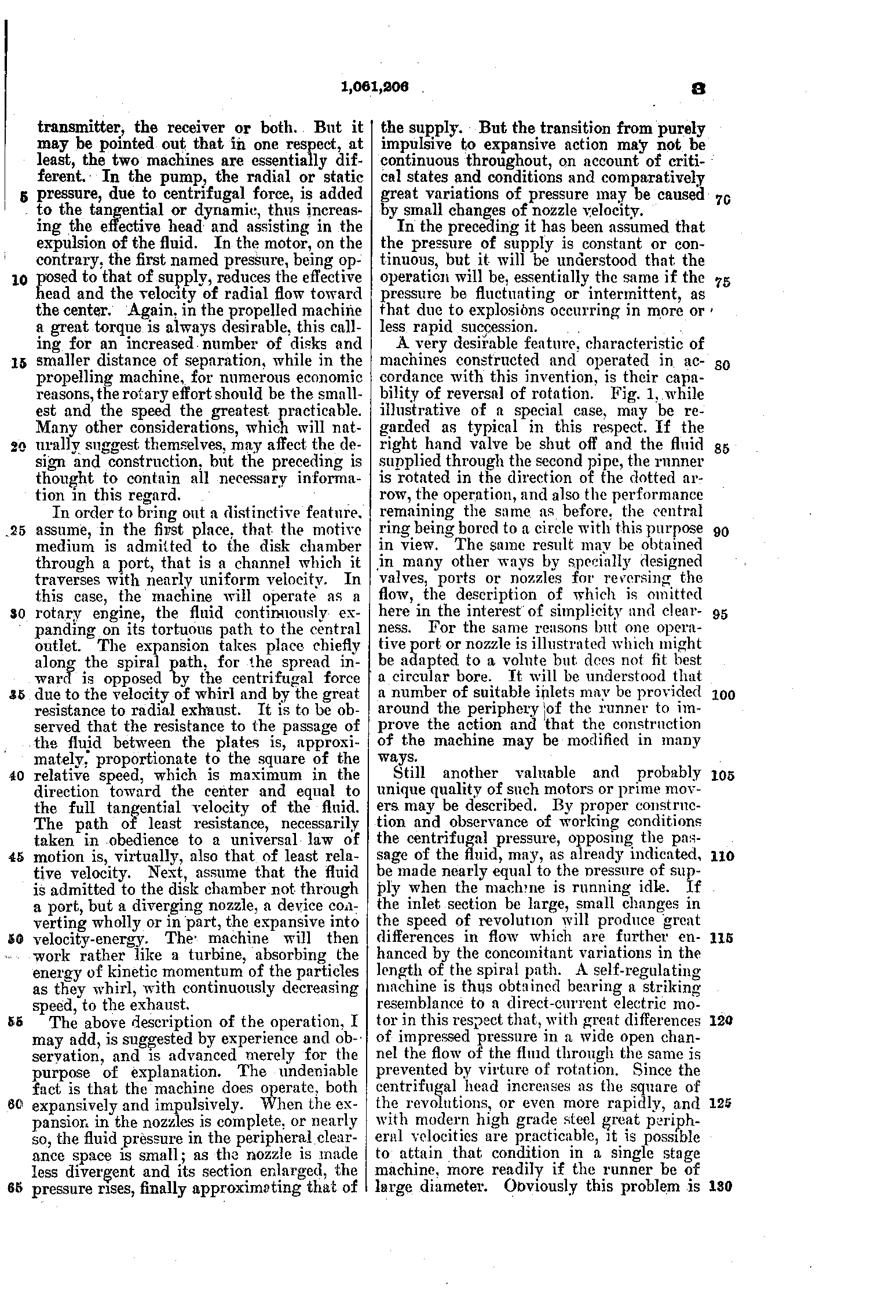
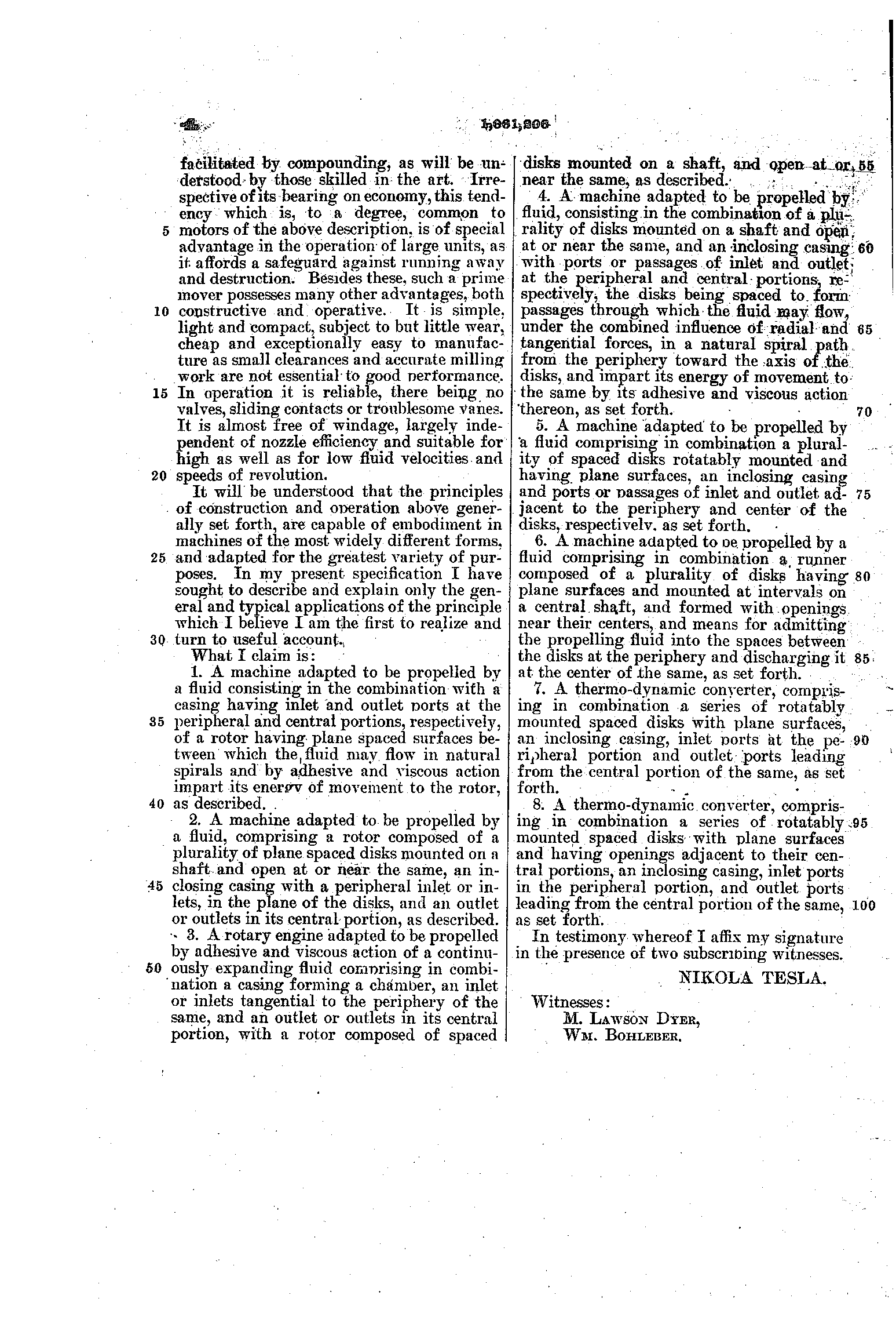
PDF · Google Patents · A division of the pump application of 1909.
US 1,061,142, Nikola Tesla, Fluid Propulsion, filed 21 October 1909, granted 6 May 1913
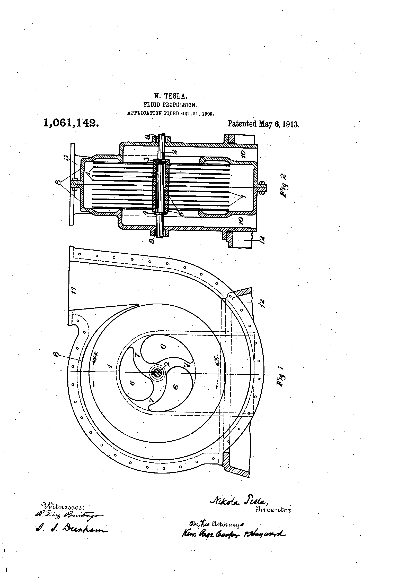
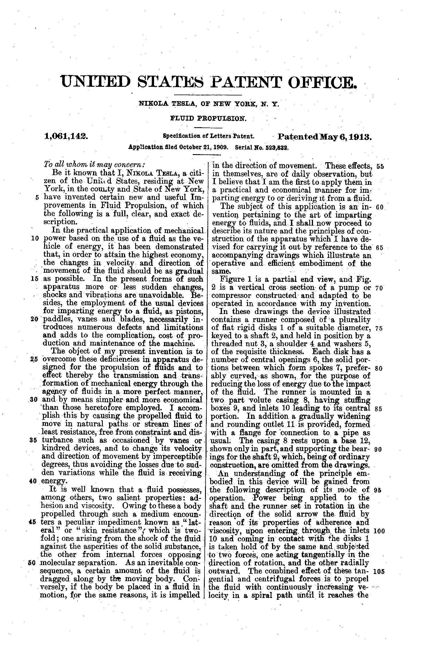
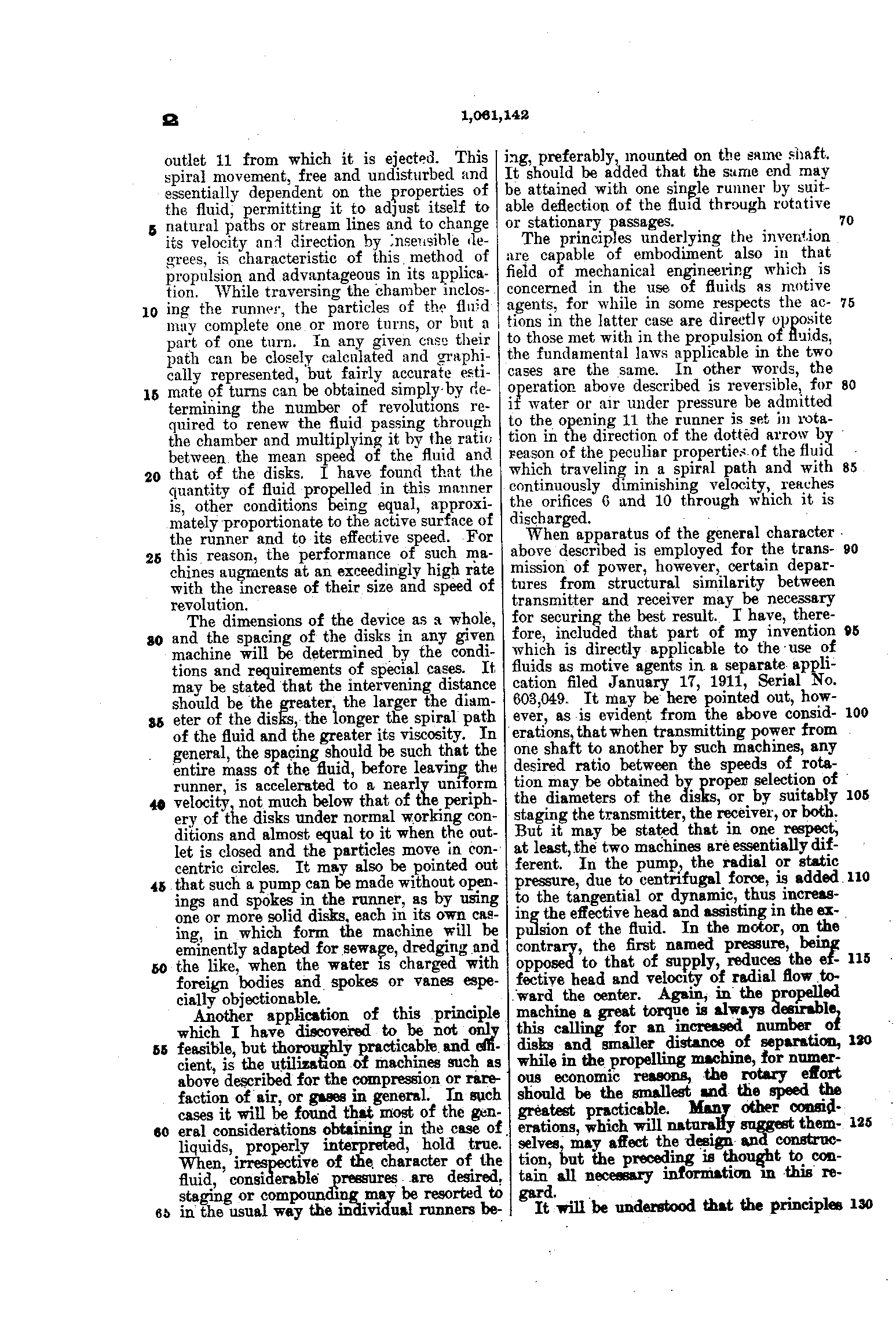
US 1,209,359, Nikola Tesla, Speed-Indicator, filed 29 May 1914, granted 19 December 1916, assignor to Waltham Watch Company
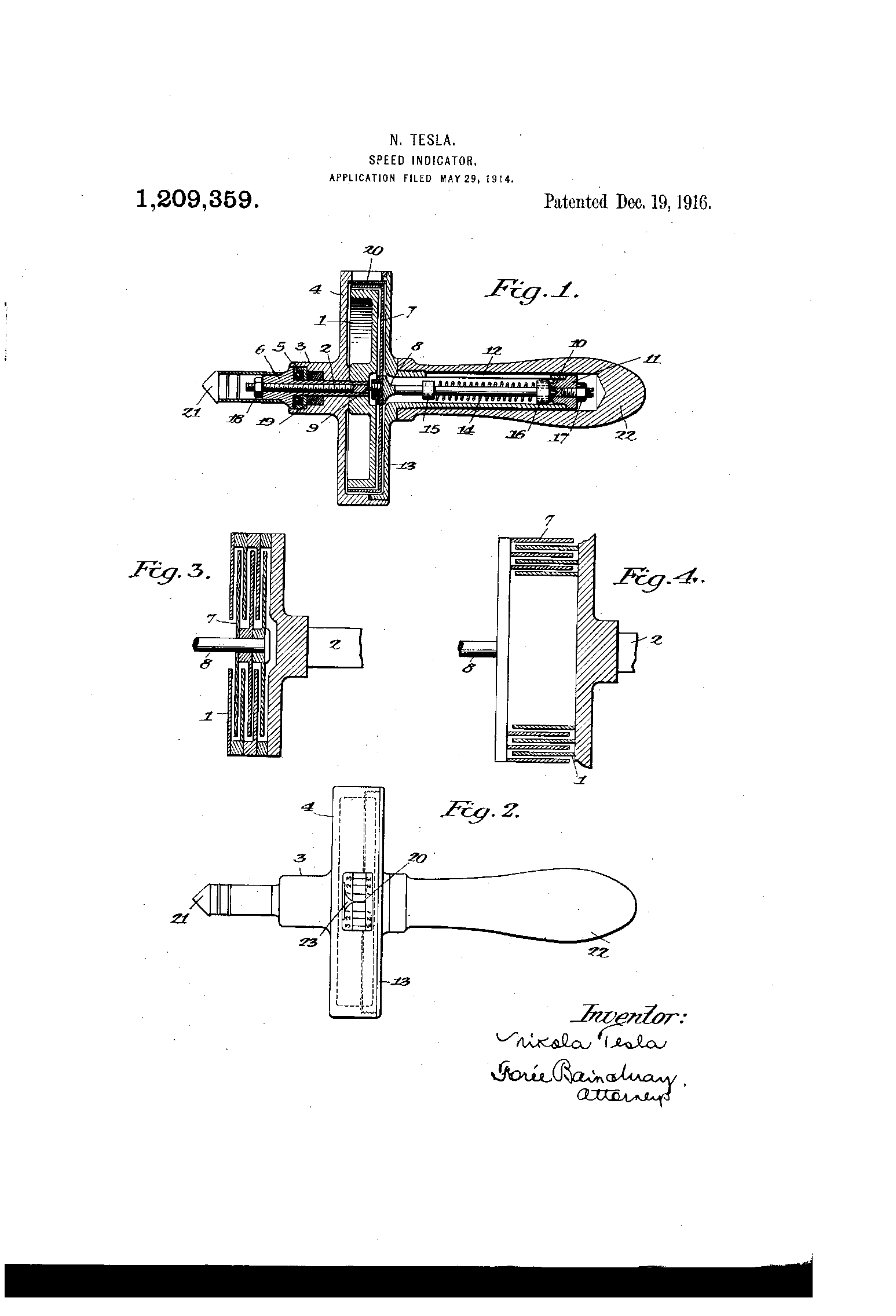
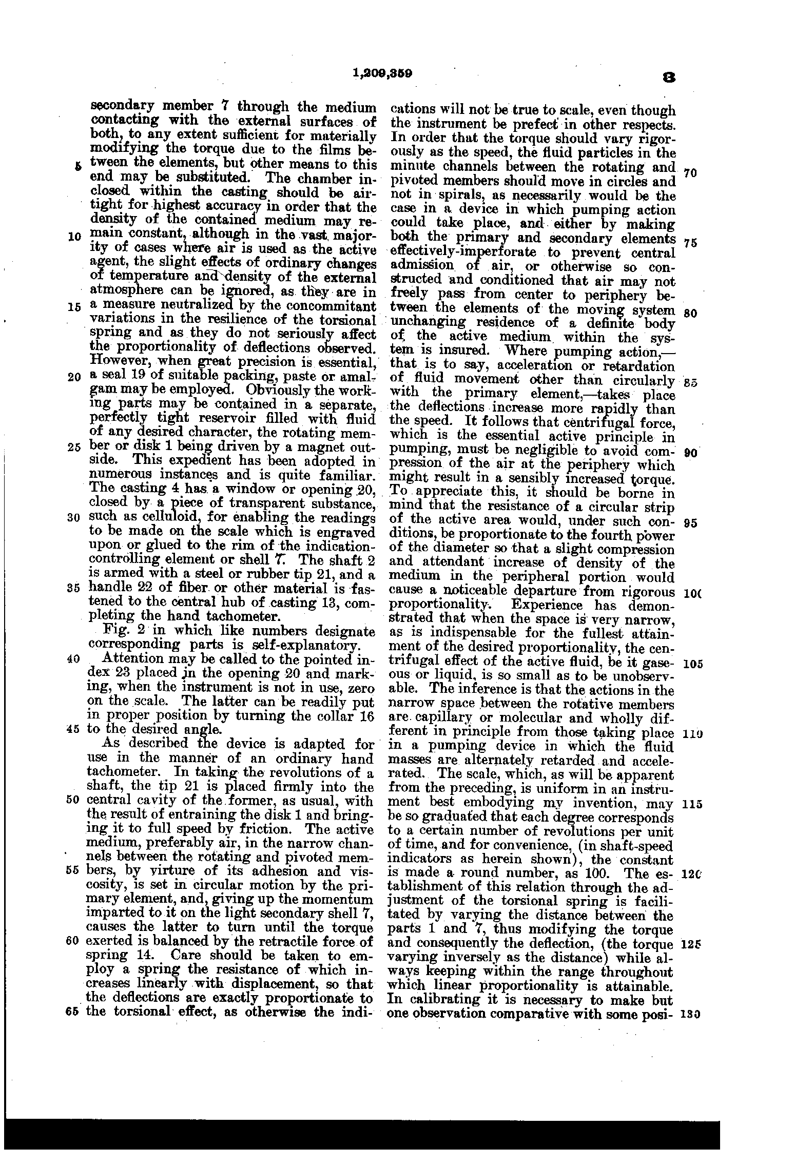
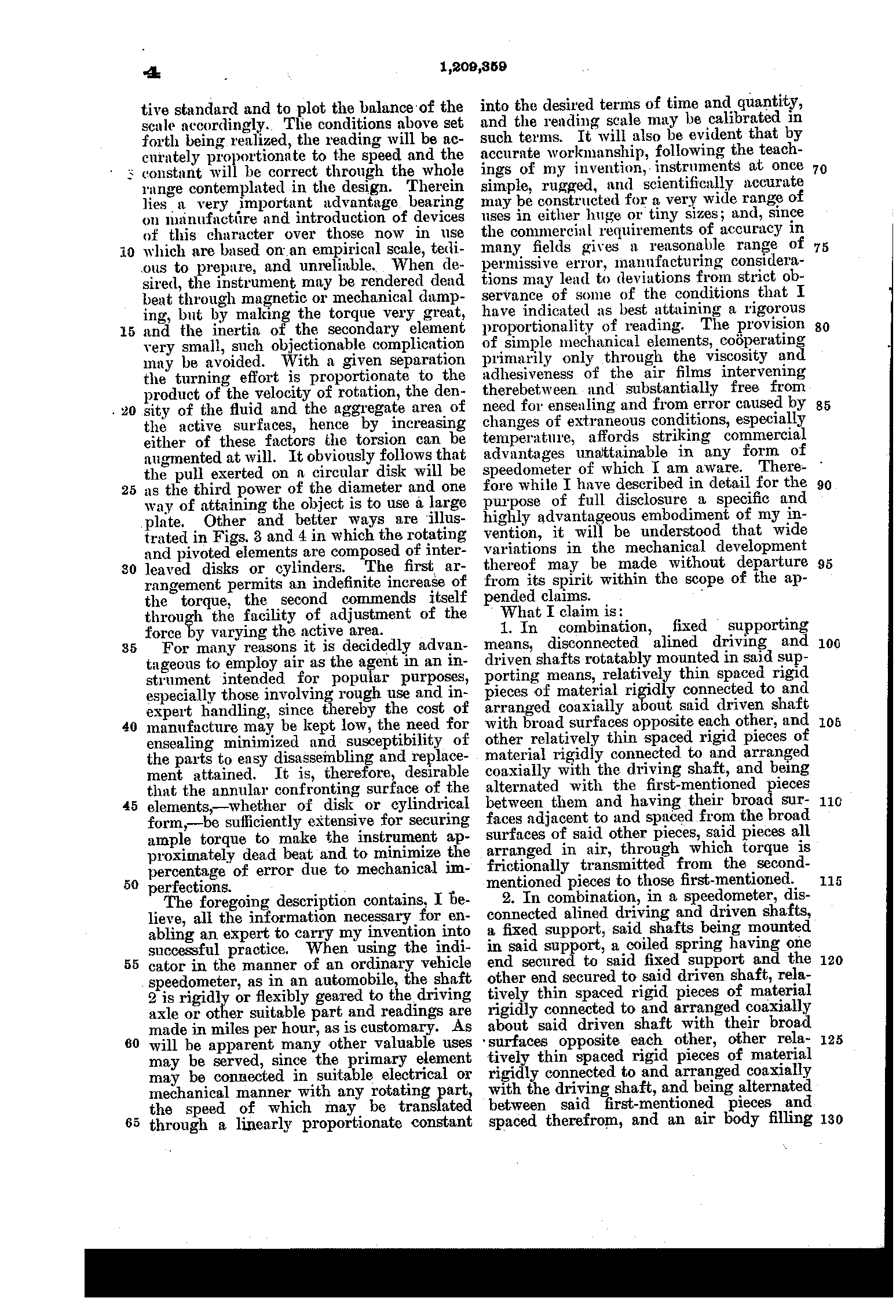
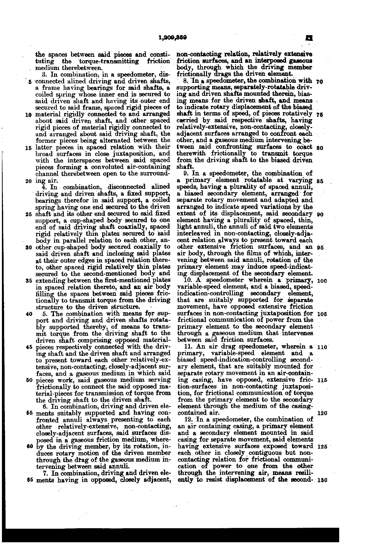
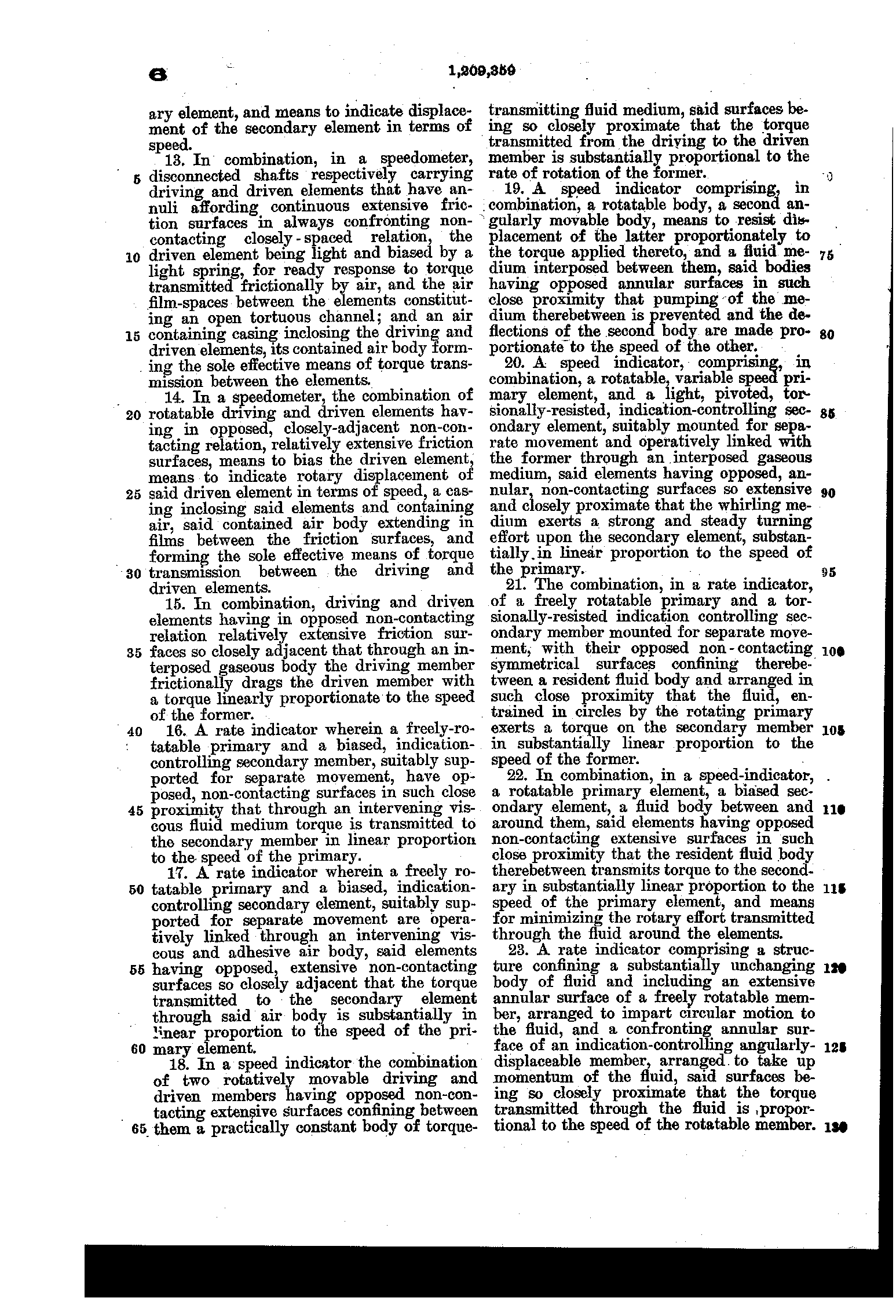
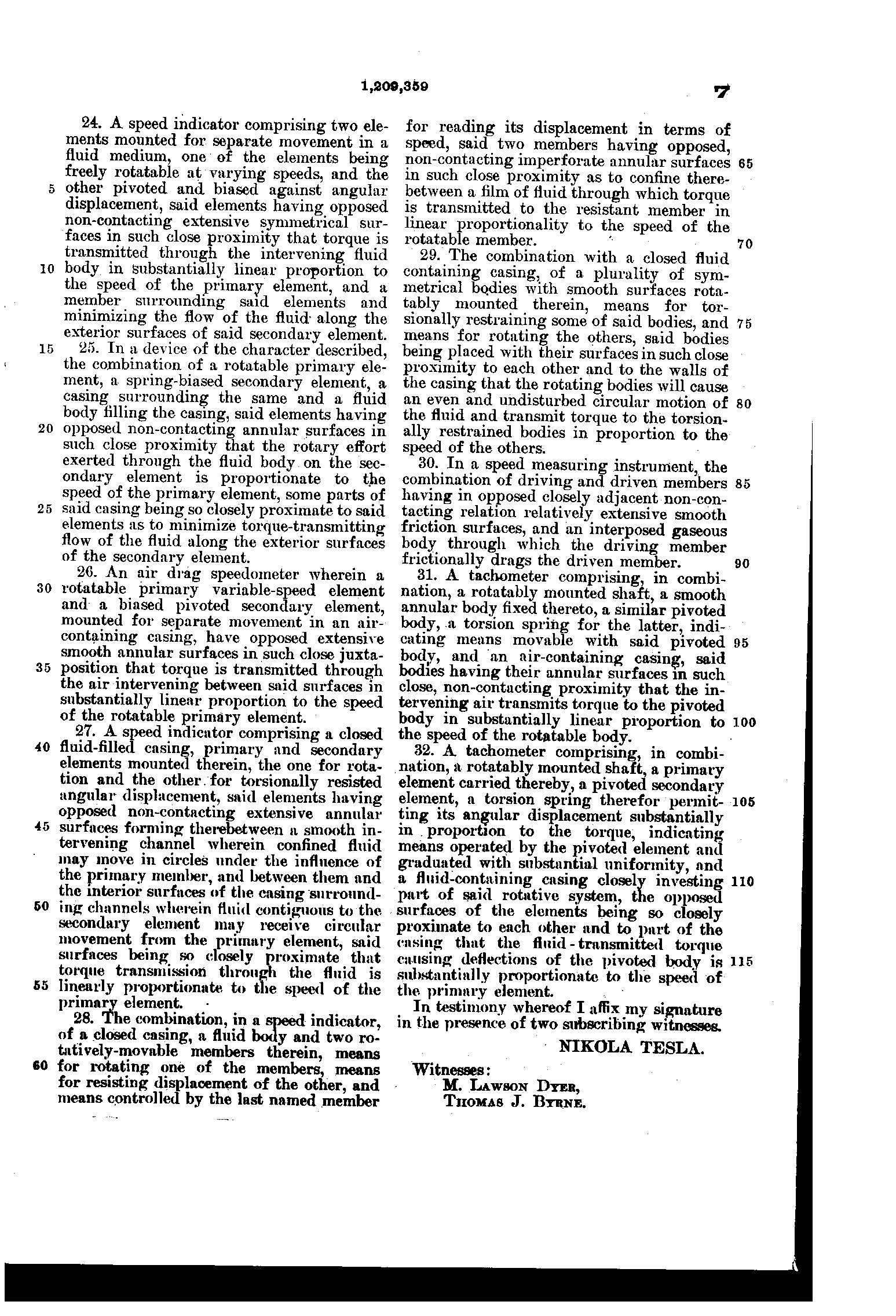
PDF · Google Patents · Figs. 3 and 4: interleaved disks, interleaved cylinders.
US 1,365,547, Nikola Tesla, Flow-Meter, filed 18 December 1916, granted 11 January 1921, assignor to Waltham Watch Company
US 1,655,114, Nikola Tesla, Apparatus for Aerial Transportation, filed 4 October 1927, granted 3 January 1928
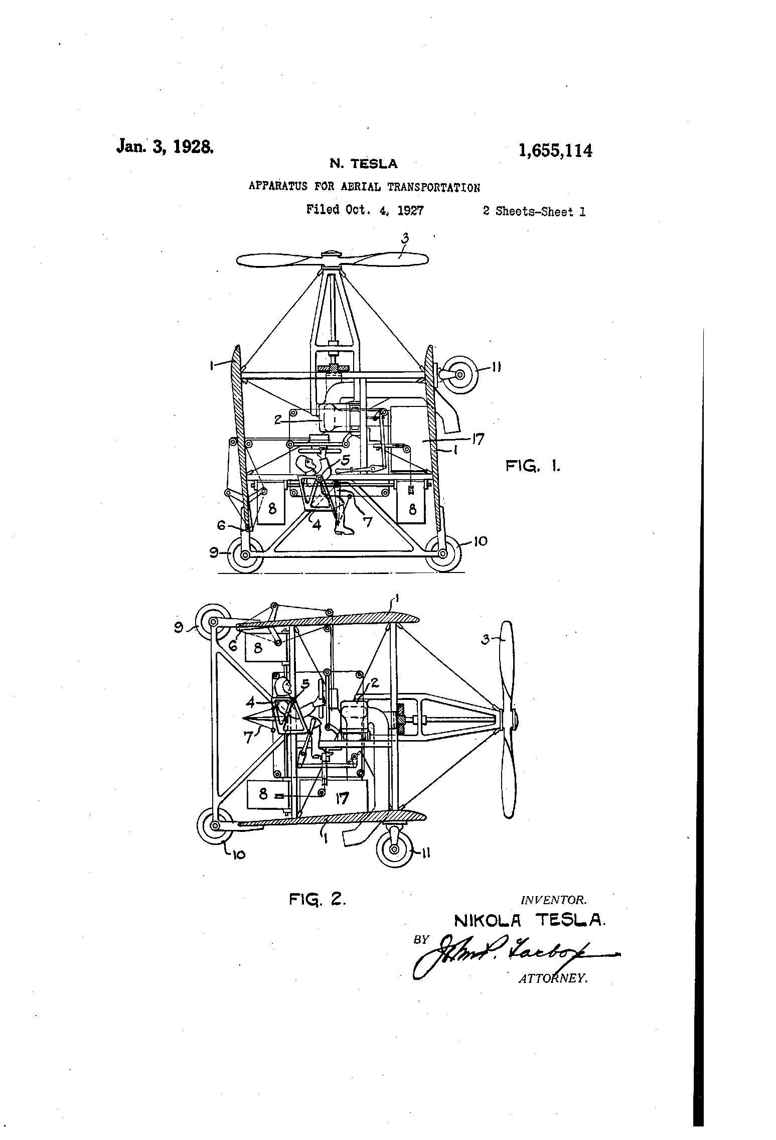
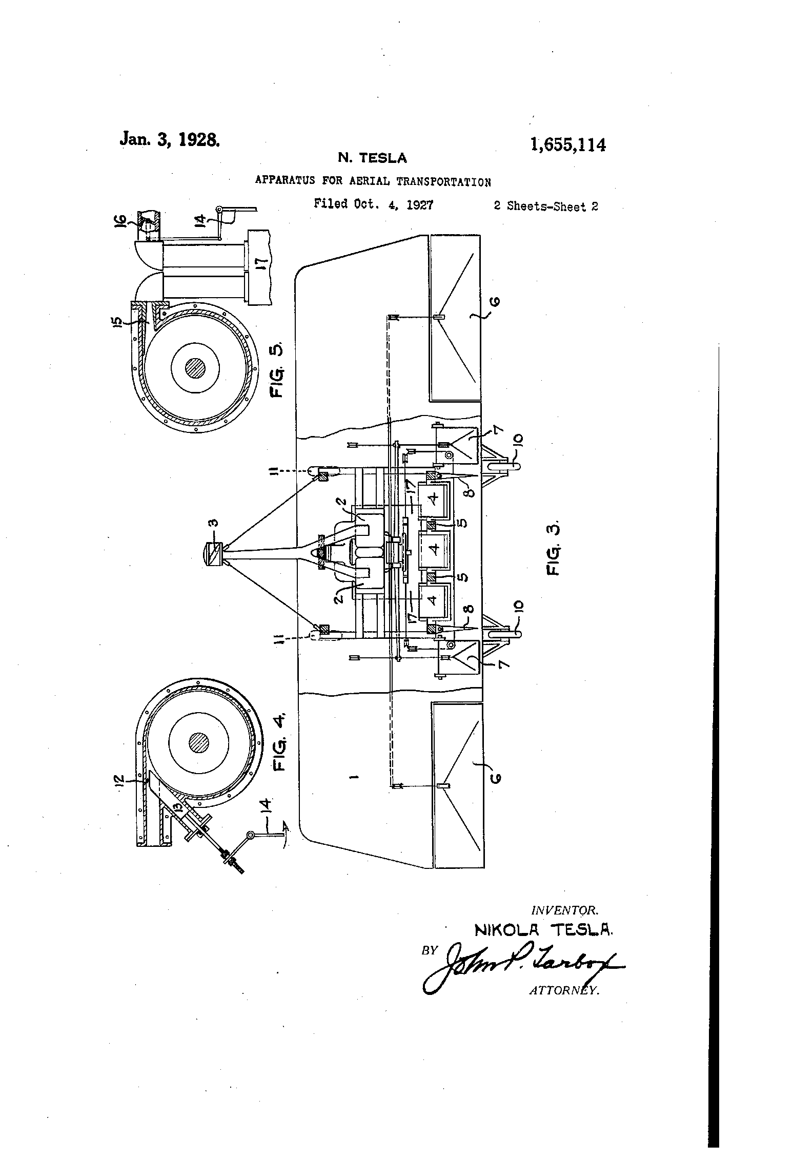
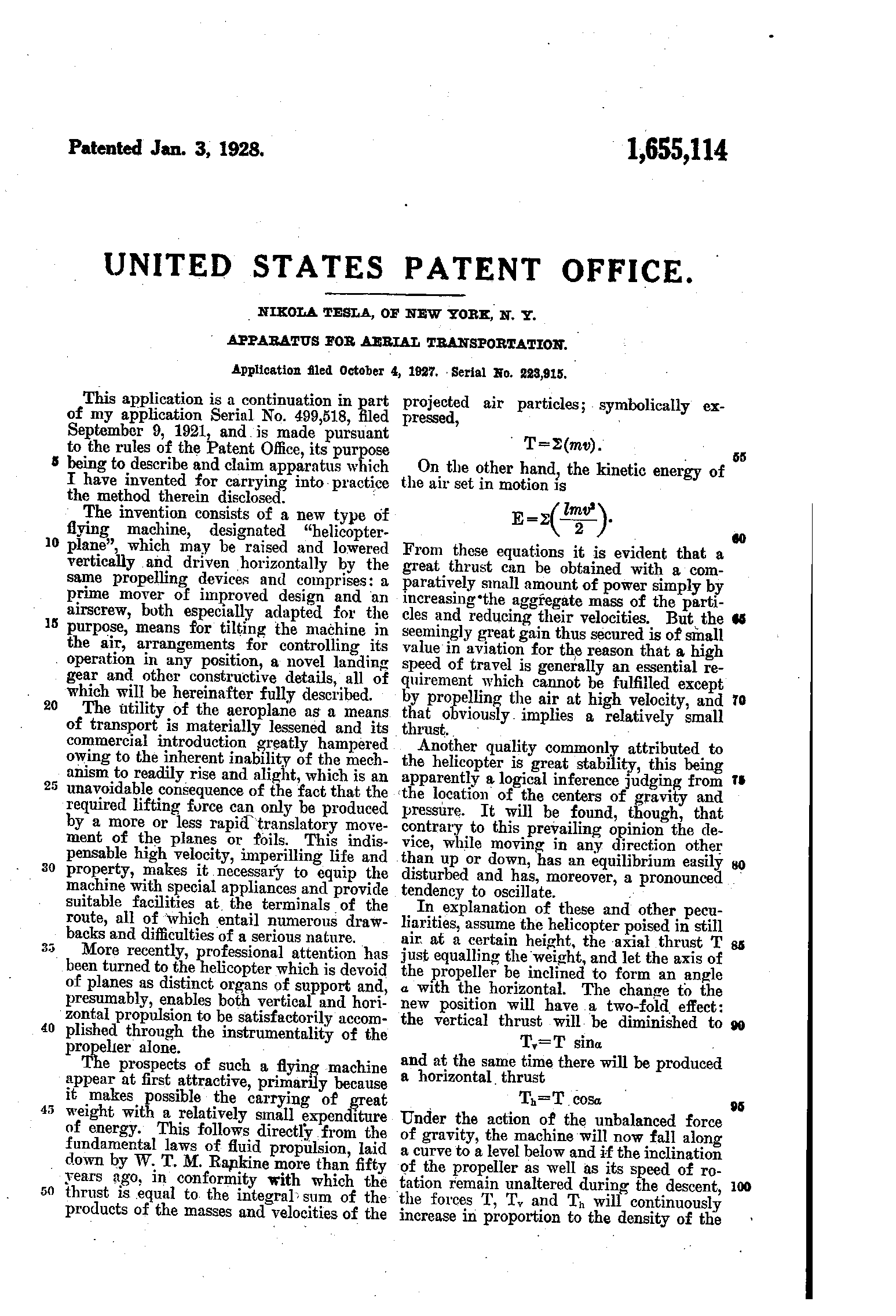
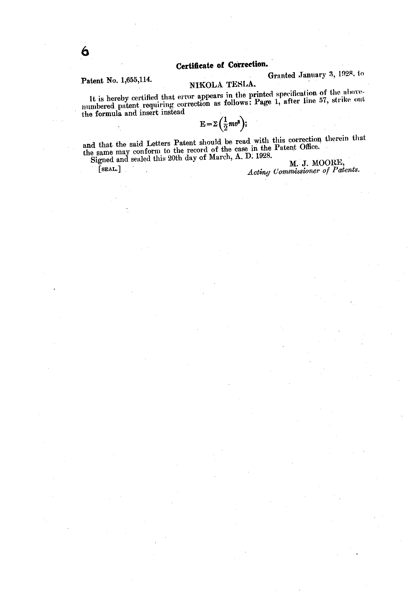
PDF · Google Patents · A continuation in part of an application of 9 September 1921.
US 1,093,166, Stead A. Asquith, Speedometer, filed 5 December 1913, granted 14 April 1914
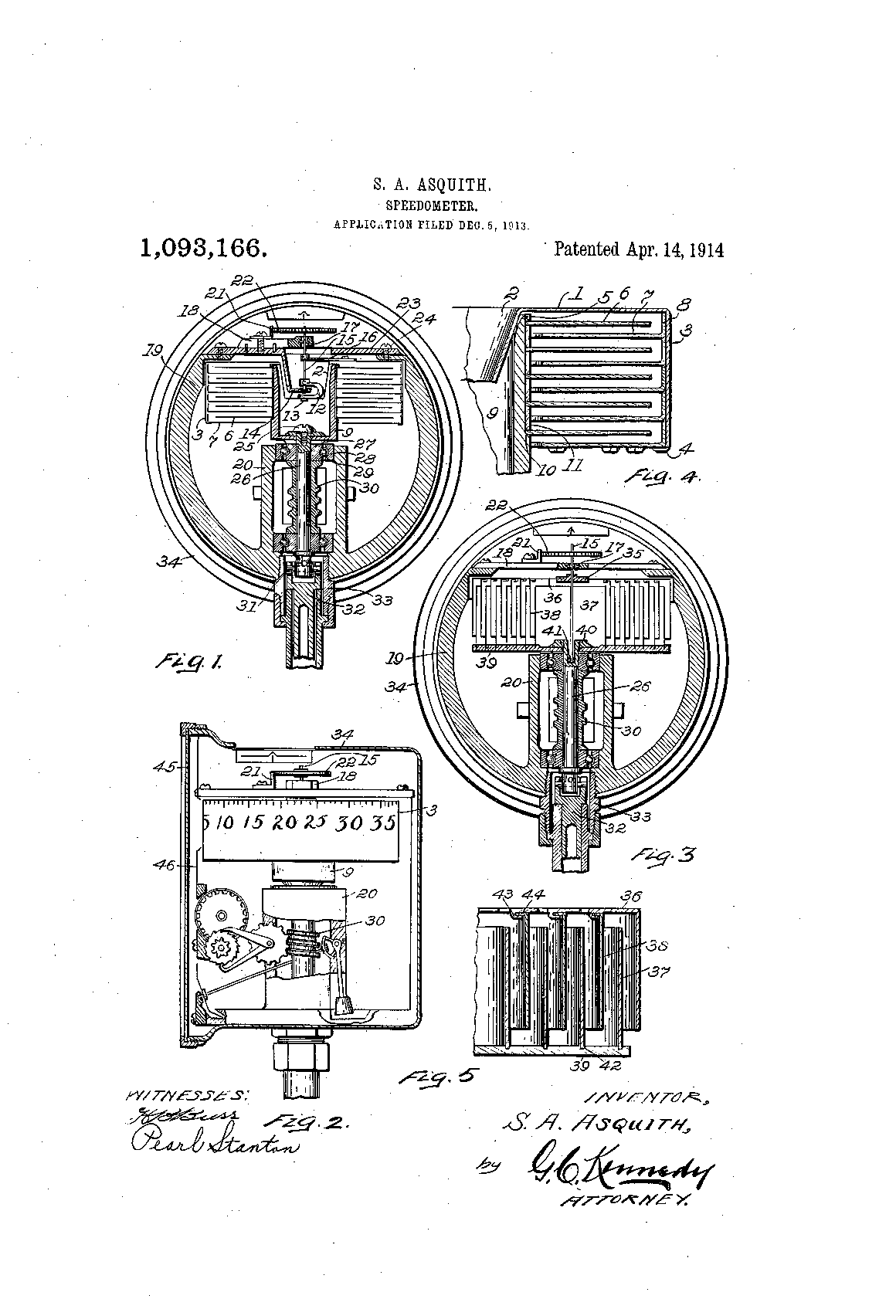
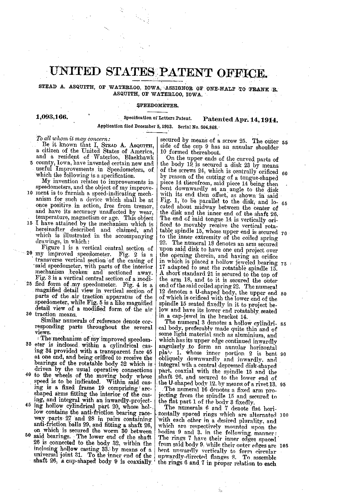
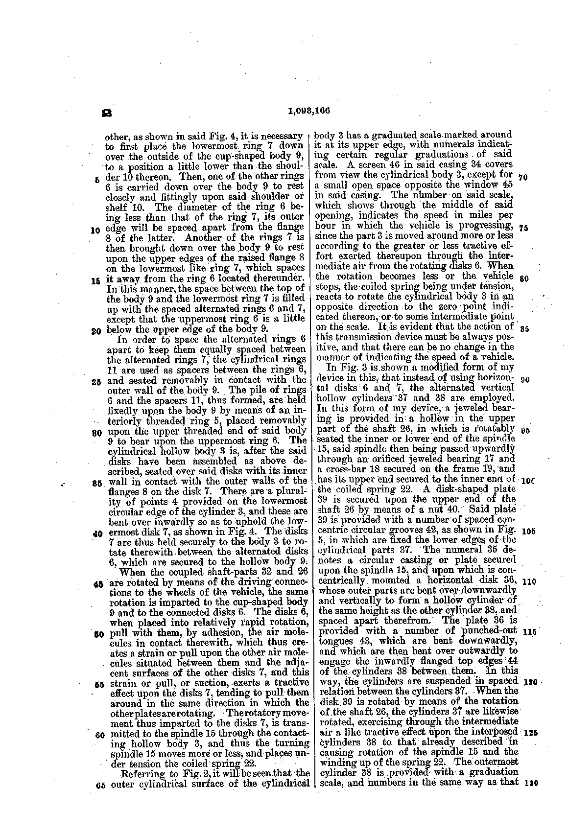
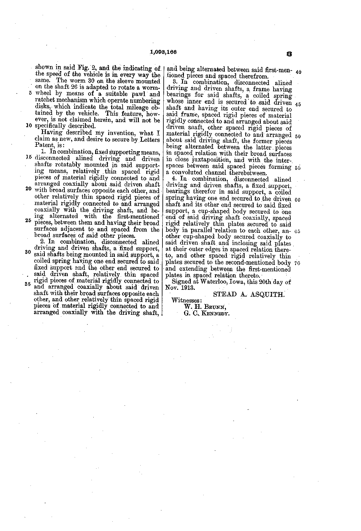
PDF · Google Patents · Asquith assigned one half to Frank R. Asquith.
US 1,282,725, Stead A. Asquith, Speed-Indicator, filed 5 February 1916, granted 29 October 1918, assignor to Waltham Watch Company
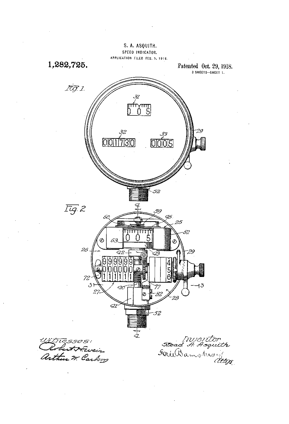
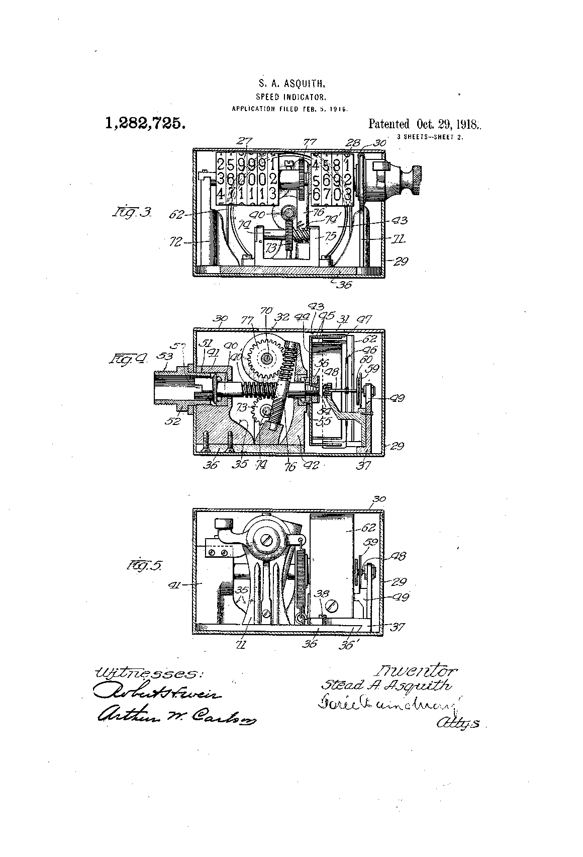
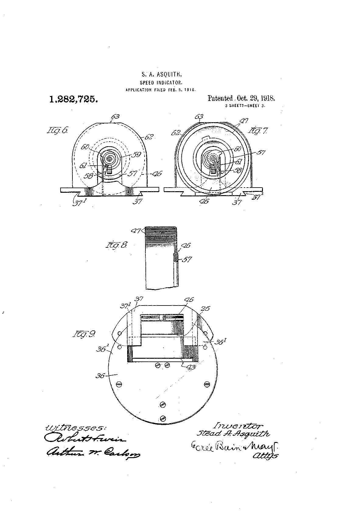
PDF · Google Patents · Divided from an application of 24 July 1915.
Sources
Every fact on this page comes from these, as in the episode. Where we have read a source only second-hand, or only as a machine reading of the page, the text says so.
Patents
- N. Tesla, Turbine, US Patent 1,061,206, filed 17 January 1911, granted 6 May 1913: the disks and their parts, "adhesion and viscosity", "of daily observation", the spiral path and how it changes with load, "the operation is reversible".
- N. Tesla, Fluid Propulsion, US Patent 1,061,142, filed 21 October 1909, granted 6 May 1913: the pump, "continuously increasing", "transmitting power from one shaft to another".
- N. Tesla, Speed-Indicator, US Patent 1,209,359, filed 29 May 1914, granted 19 December 1916, assignor to Waltham Watch Company: the parts, the gap, "interposed thin films of air", "circles and not in spirals", "uniformly graduated", Figs. 3 and 4.
- N. Tesla, Ship's Log, US 1,314,718 (1919); Flow-Meter, US 1,365,547 (1921); Frequency Meter, US 1,402,025 (1922): all assigned to Waltham.
- N. Tesla, Apparatus for Aerial Transportation, US Patent 1,655,114, granted 3 January 1928: "helicopter-plane", the turbines of 1,061,206, the seats, the overload.
- S. A. Asquith, Speedometer, US Patent 1,093,166, filed 5 December 1913, granted 14 April 1914; Speed-Indicator, US Patent 1,282,725, granted 29 October 1918, assignor to Waltham Watch Company.
History
- "Tesla Promises Big Things", The Sun (New York), 12 September 1911, p. 3: the interview, "no planes, no screw propellers", the 110 horsepower machine.
- "The Tesla Steam Turbine", Scientific American 105:14 (30 September 1911), p. 296: Waterside, 200 horsepower at 9,000 r.p.m., 38 pounds of steam per horsepower-hour, a third of the heat, "less than 12 pounds".
- F. P. Stockbridge, "The Tesla Turbine", The World's Work 23:5 (March 1912), pp. 543–548: the visit to Waterside and Tesla's words there, the derby hat, the flying machine, "on the market long before that"; the photographs.
- J. A. Moyer, Steam Turbines, 2nd ed. (New York: Wiley, 1914), preface, p. vii.
- J. A. Ewing, "Steam Engine", Encyclopaedia Britannica, 11th ed. (1911), the turbine sections: the bladed turbines' consumption.
- J. J. O'Neill, Prodigal Genius: The Life of Nikola Tesla (1944), pp. 197–198: the Allis-Chalmers turbines as reported by Hans Dahlstrand, and Tesla's answer.
- "Nikola Tesla Admits That He's Bankrupt", The Evening World (New York), 17 March 1916, p. 10. Read in the Library of Congress's machine reading of the page.
- "Waltham Speedometer", The Automobile 34 (30 March 1916), pp. 580–582: the announcement and the first lot of 25,000. Read in the copy reproduced in J. Behary, Tesla Speedometer Files (2020).
- Waltham Speedometer: Made in the Largest Watch Factory in the World (Waltham Watch Co., 1916): Packard's tests, the cups, the price list, heat, cold and altitude.
- Waltham advertisements, Evening Public Ledger (Philadelphia), 18 May 1921, p. 9 and 29 June 1921, p. 15.
- K. M. Swezey, "How Tesla Evolved Epoch-Making Discoveries", East St. Louis Daily Journal, 4 April 1926, p. 40.
- "Tesla Receives Patents for His Helicopter Plane", New York Herald Tribune, 22 February 1928, p. 3, read only as a transcription.
- L. Zaharoni, "Charles River Museum exhibit shows Nikola Tesla as fraught businessman", Waltham Times, July 2026: the royalty of twenty cents, the letters, "added prestige", 1933.
- W. H. Terbo, letter of 6 April 2007, reproduced in Behary (2020): Tesla's letter of 16 May 1929 as he described it. We have not seen the 1929 letter.
- W. Rice, "Tesla Turbomachinery", Proceedings of the IV International Nikola Tesla Symposium, Belgrade, 1991.
- Thomazoni et al., "Influence of operational parameters on the performance of Tesla turbines", Energy 261 (2022) 125159.
- Pei, Liu and Ooi, "Research on Energy-Efficient Disc Pumps", Machines 11 (2023) 954.
- The forty per cent at Waterside is our own calculation from steam tables, for saturated steam at 125 pounds per square inch expanding to the open air.
- Dollar amounts in today's money: the ratio of annual-average consumer prices, from the Federal Reserve Bank of Minneapolis, "Consumer Price Index, 1800-", with 2025 as today, rounded to two figures. The twenty cents is taken at 1928; the letters are dated only "the late 1920s", and 1927 to 1929 give the same figure.
Images
- Patent drawings and specifications: USPTO, public domain.
- The World's Work (1912), Waltham Speedometer (1916, scan from the Boston Public Library via the Internet Archive) and Moyer (1914): published in the United States before 1931, public domain; scans via the Internet Archive.
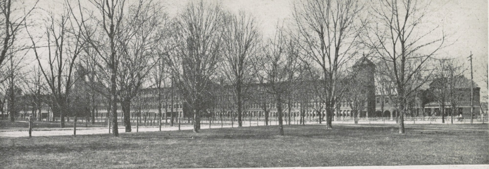
- Waltham Watch Company, 1906: Library of Congress, Prints & Photographs Division, LCCN 2013647093, no known restrictions on publication.
- Nikola Tesla in his New York laboratory, 1922: photo by the Nikola Tesla Museum, licensed CC BY-SA 4.0, via Wikimedia Commons. Shown whole and unaltered.