 Curious Patents
Tesla's Earthquake Machine, and the Valve With No Moving Parts
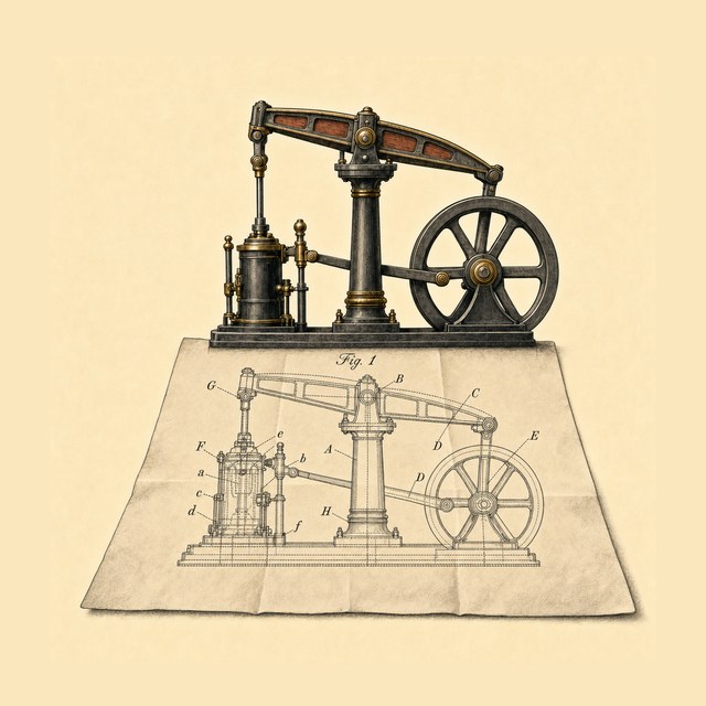
In 1893 Nikola Tesla showed Chicago an engine with no flywheel that kept time like a pendulum. In 1935 he said a small one had once shaken his neighbourhood like an earthquake. In 1916 he drew it driving a valve with nothing inside that moves. Run the engine cut in half, lift the lid off the valve, watch our flow simulation go both ways, and read the patents and every source.
Watch the episode
Chicago, 1893
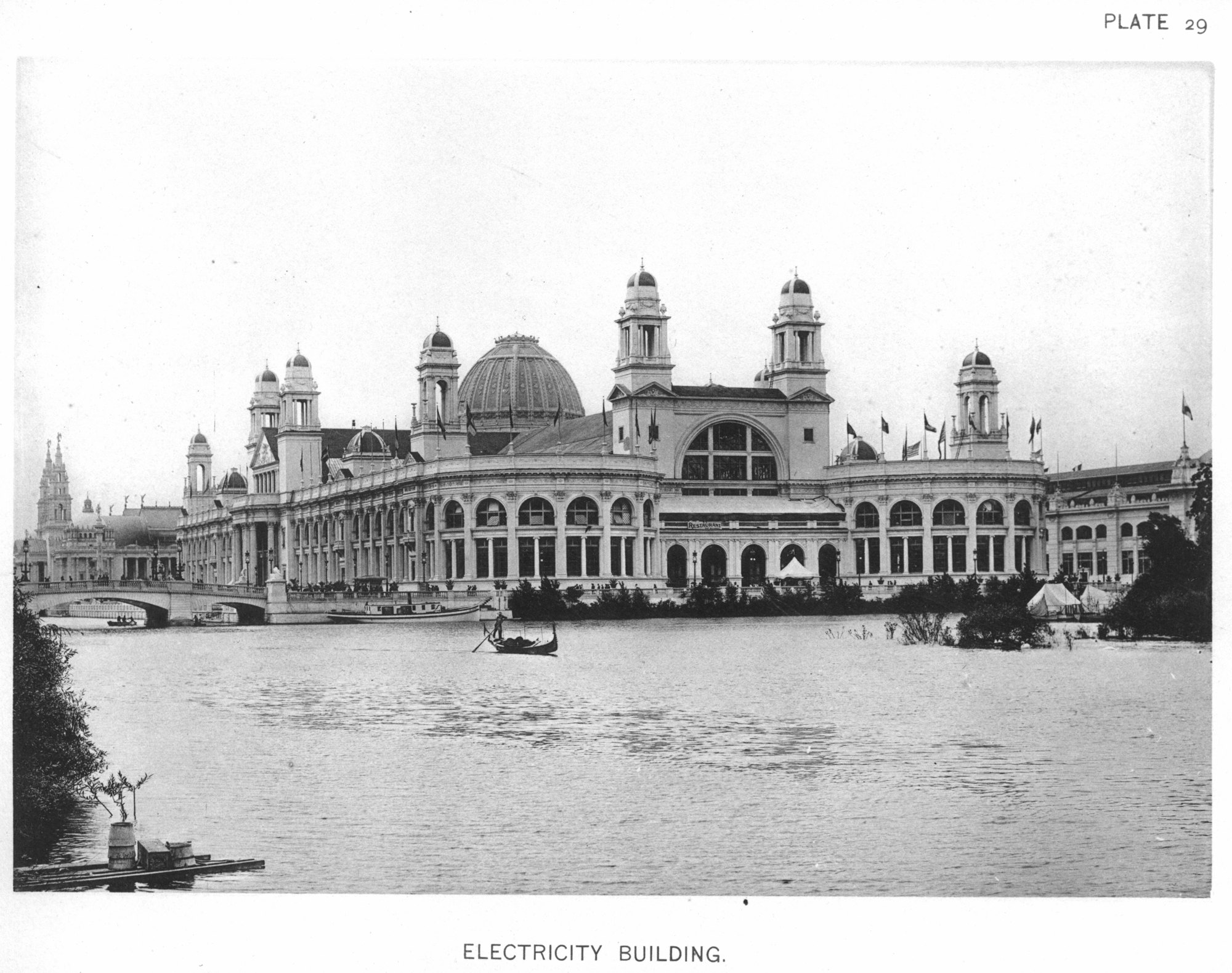
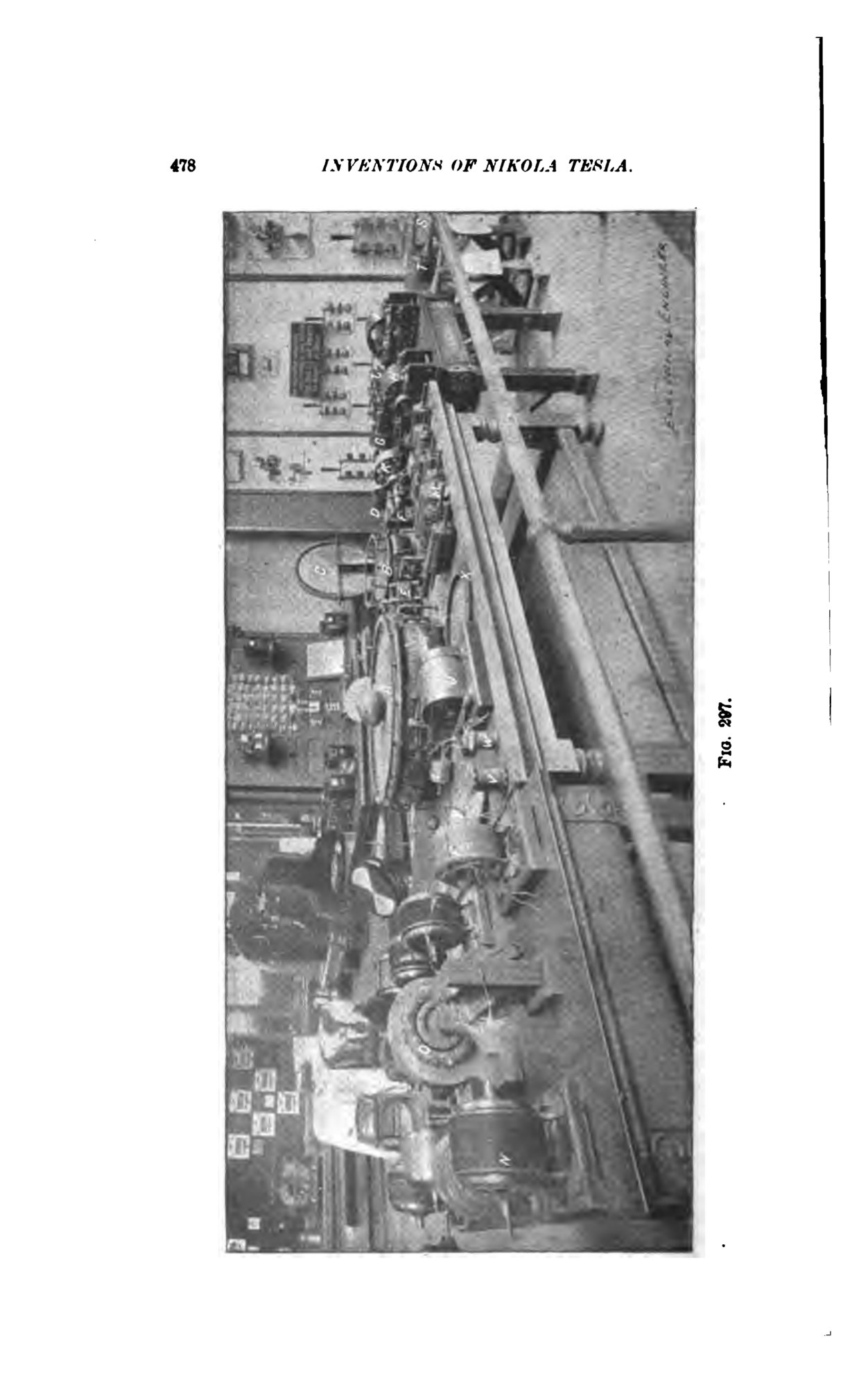
In the summer of 1893 Chicago held the World's Columbian Exposition. Tesla's apparatus, wrote his friend and publisher T. C. Martin, "occupied part of the space of the Westinghouse Company, in Electricity Building". The fair's official catalogue lists that space without his name: "429a. Westinghouse Electric & M'fg Co., Pittsburg, Pa. High tension and high frequency discharges. B-1". J. P. Barrett's account of the electrical exhibits places "a room about 25 feet square" for Tesla's high-frequency experiments "in one of the Westinghouse spaces", and outside it, "mechanical and electrical oscillators, the subject of a lecture by Mr. Tesla".
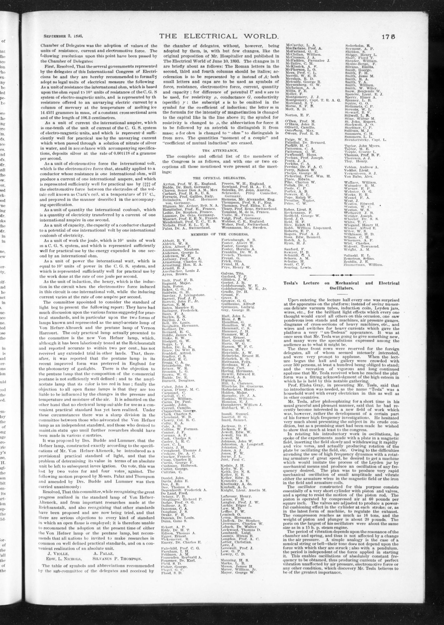
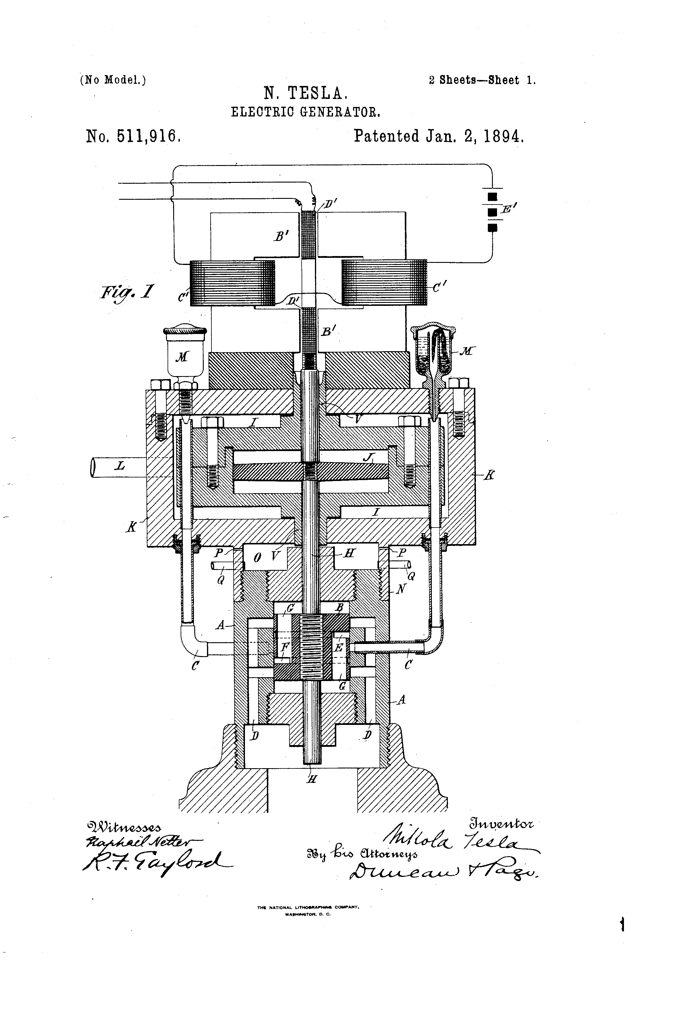
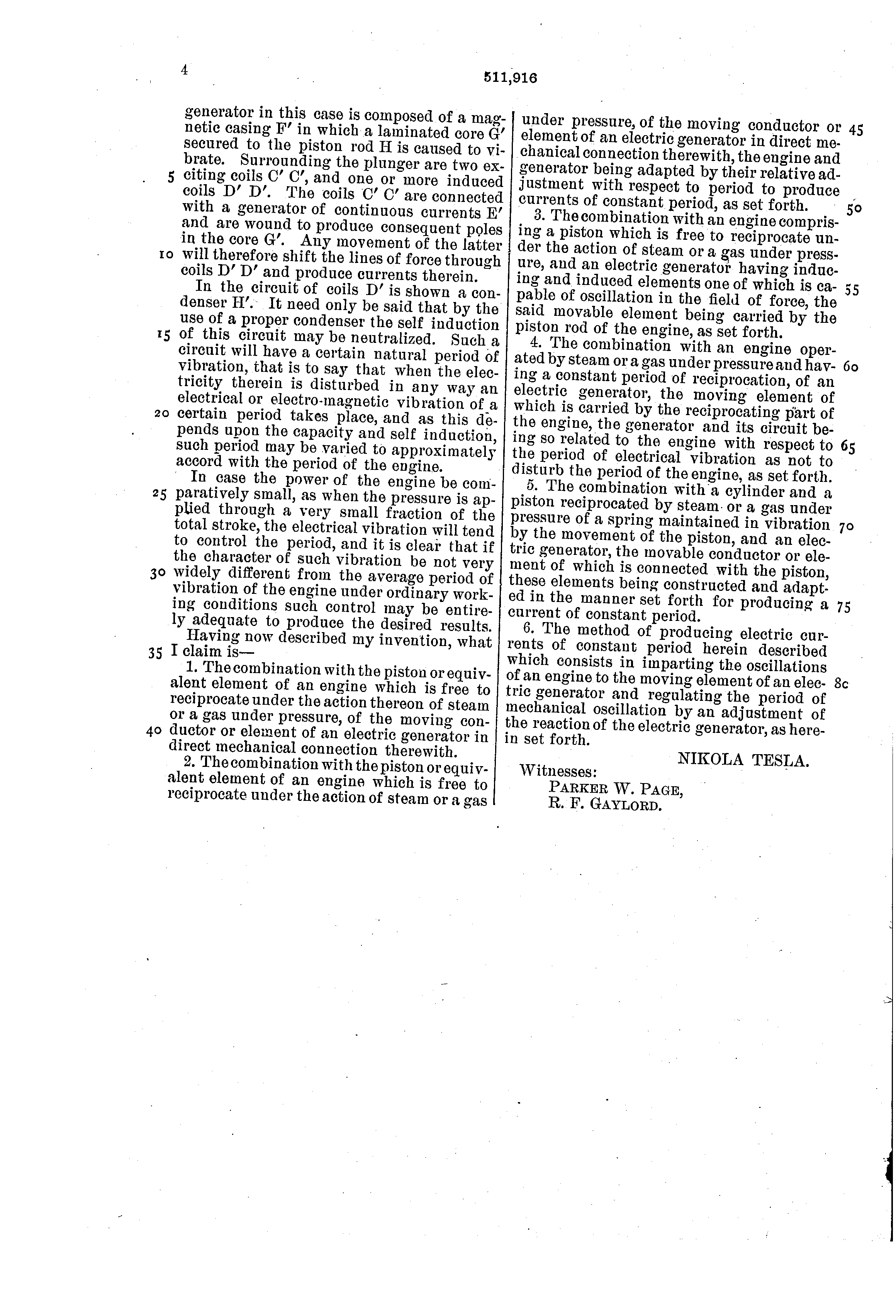
On 19 August 1893 Tesla filed two patent applications: one for an engine (granted as US 514,169) and one for an electric generator (US 511,916). Six days later, "on the evening of Friday, August 25, 1893", he lectured on his mechanical and electrical oscillators to the International Electrical Congress, "in the hall adjoining the Agricultural Building". The Congress's own record of its final meeting that afternoon has the announcement: "Mr. Tesla's lecture at eight o'clock that evening at the Agricultural Hall". Besides the apparatus in the room, Martin wrote, "he employed an air compressor, which was driven by an electric motor".
The Electrical World counted "over 500 persons, at least a hundred being obliged to stand". They had come expecting vacuum tubes and brilliant light; they found "ponderous iron stands and machines, air pressure gauges", which gave the platform "a very 'un-Teslean' appearance". The paper's editorial called the lecture "a disappointment to those who expected to be entertained with brilliant experiments".
An engine without a flywheel
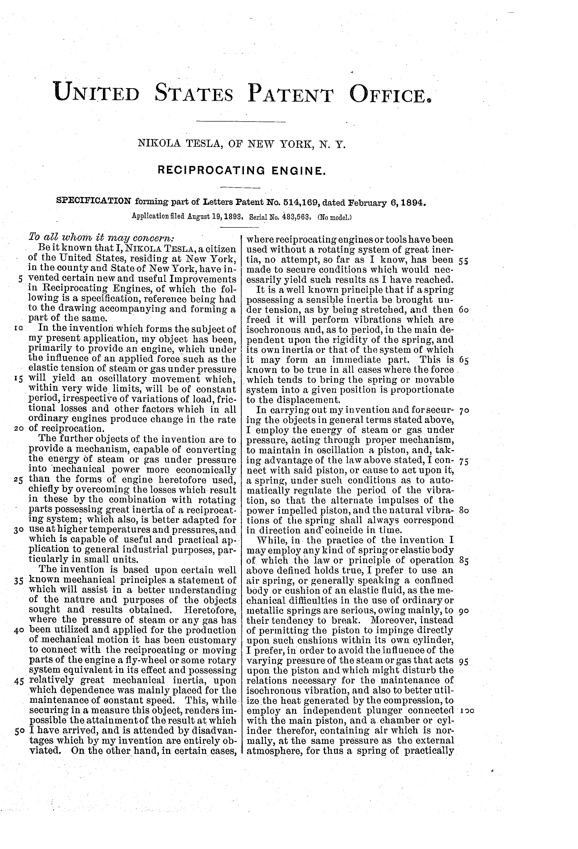
Steam engines of the day kept their speed steady with a flywheel. Tesla's patent describes the usual engine as having "a fly-wheel or some rotary system ... possessing relatively great mechanical inertia, upon which dependence was mainly placed for the maintenance of constant speed", and says that this "renders impossible the attainment of the result at which I have arrived". His engine throws the flywheel away.
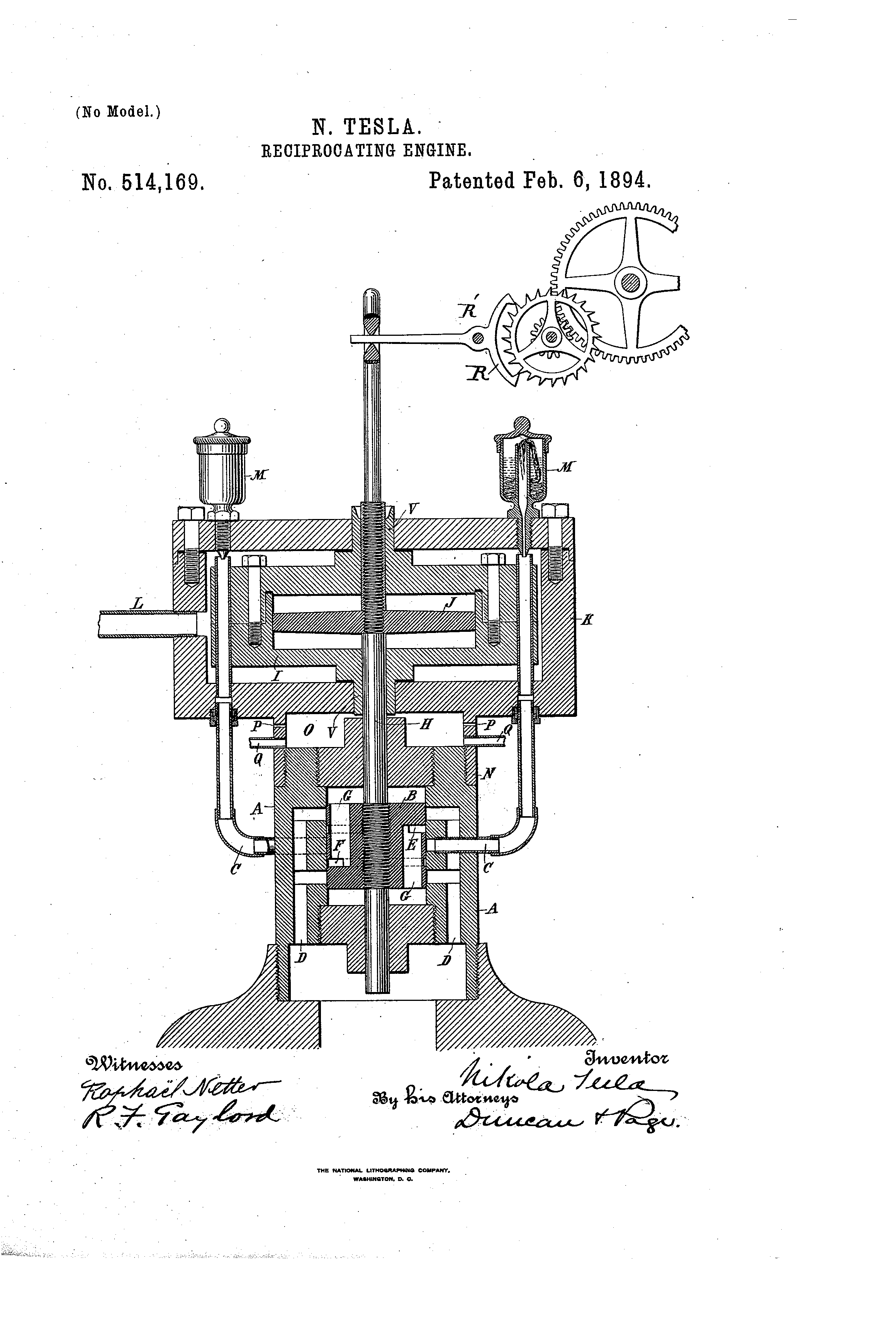
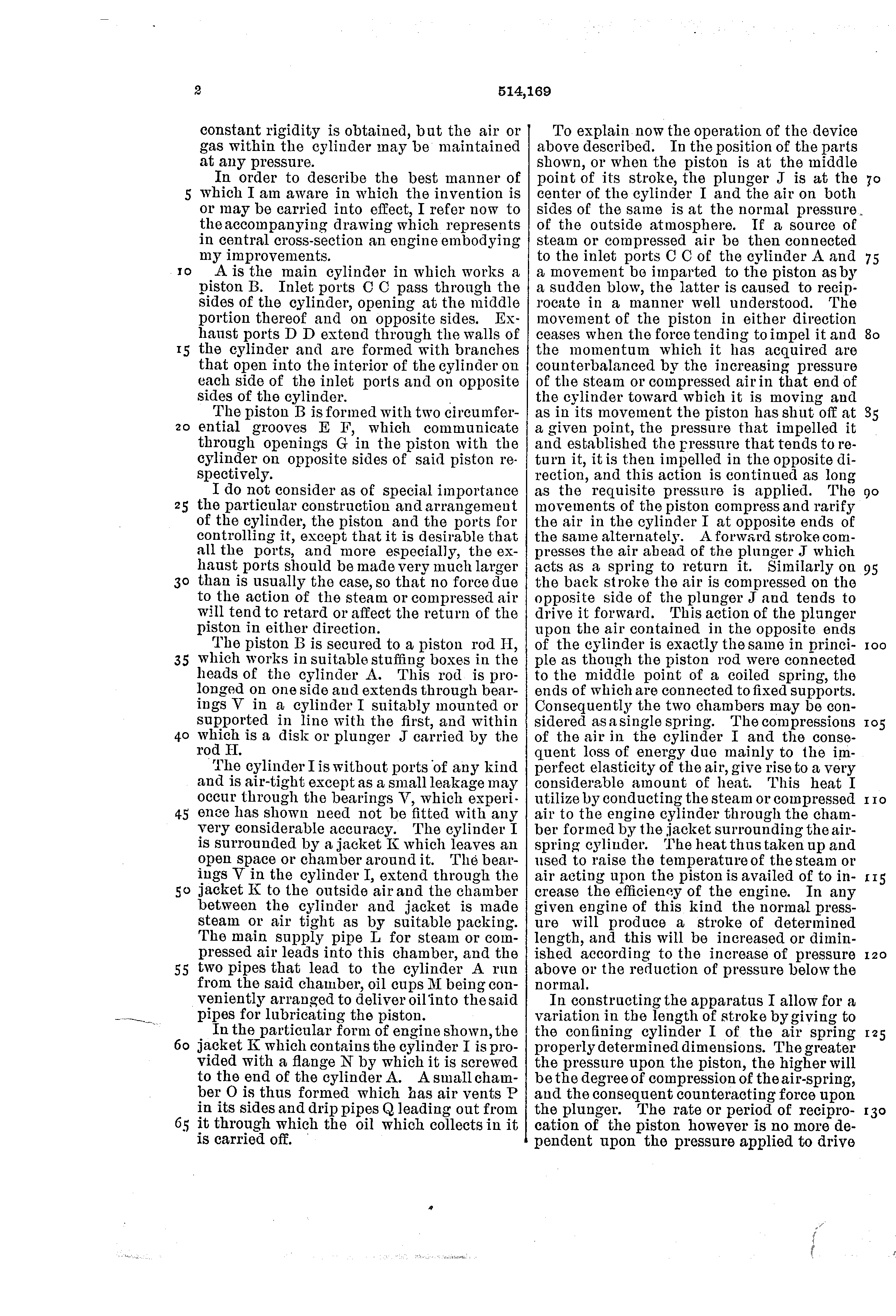
Steam or compressed air comes in through ports C C, "opening at the middle portion" of the cylinder A. The piston B, as it moves, "has shut off at a given point, the pressure that impelled it and established the pressure that tends to return it", so it drives itself back and forth. To start it, the patent says, give the piston a movement "as by a sudden blow".
The rod H runs on into a second cylinder I, "without ports of any kind", with a plain disk or plunger J inside. "A forward stroke compresses the air ahead of the plunger J which acts as a spring to return it." Tesla's own picture of it: "exactly the same in principle as though the piston rod were connected to the middle point of a coiled spring, the ends of which are connected to fixed supports".
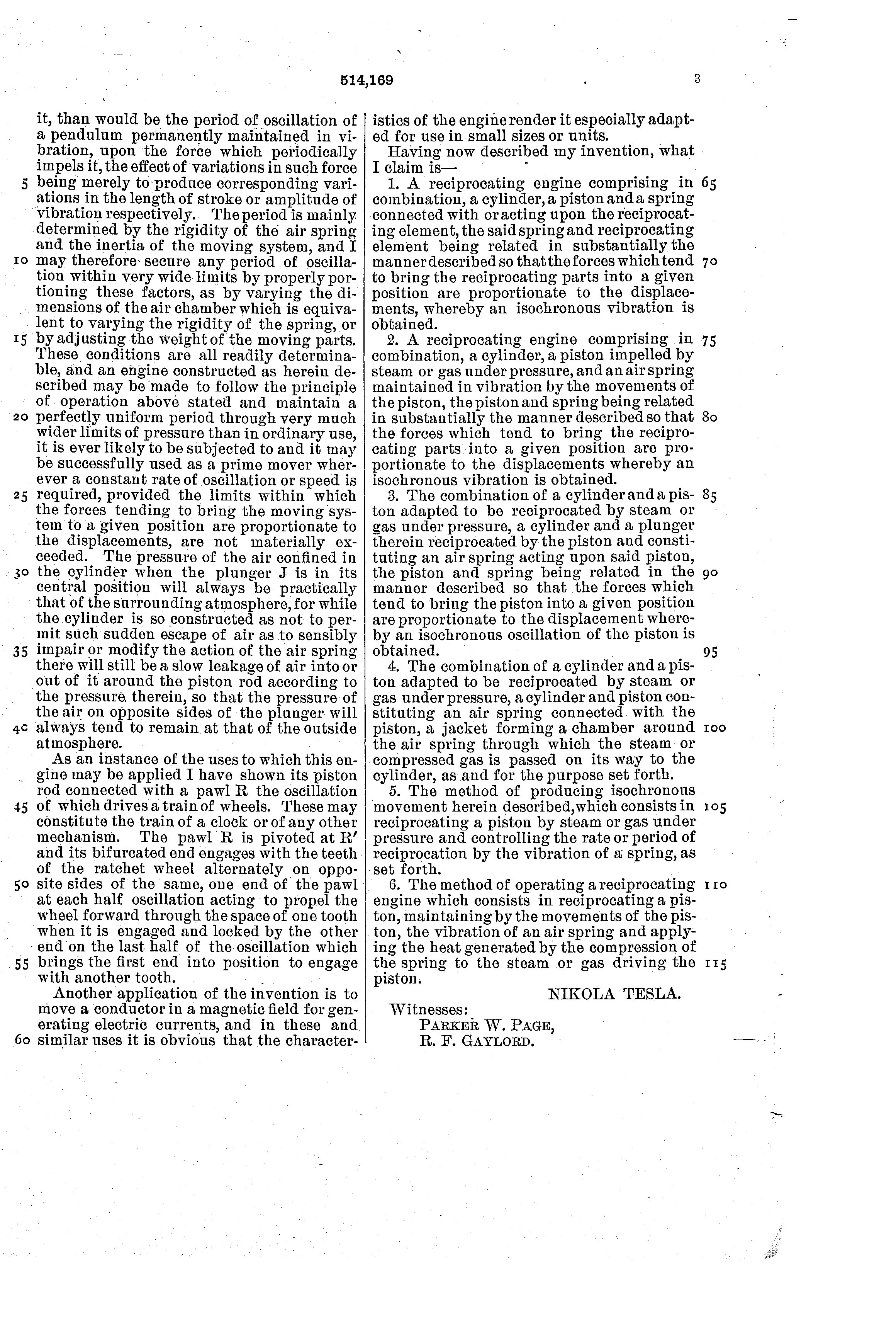
A weight on a spring swings at its own rate: push it harder and it swings further, not faster. That is the whole point of the patent. "The rate or period of reciprocation of the piston however is no more dependent upon the pressure applied to drive it, than would be the period of oscillation of a pendulum permanently maintained in vibration, upon the force which periodically impels it." More pressure gives a longer stroke. To change the rate, change the spring or the weight: "by varying the dimensions of the air chamber ... or by adjusting the weight of the moving parts".
And the drawing shows what a steady beat is good for. A forked pawl R on the end of the rod pushes a ratchet wheel round, half a tooth at each half swing, and the wheel turns a train of gears, which "may constitute the train of a clock". (The text says one tooth each half oscillation; the drawing's layout, a pivot beside the wheel, gives half a tooth, and our model follows the drawing.)
From the patent's one drawing, cut in half as it is drawn: cylinder A and piston B with its grooves E and F; the inlets C and exhausts D; rod H; the sealed cylinder I and plunger J; the jacket K that the supply passes through on its way in by L, and the pipes with oil cups M; the flange N; the pawl R on its pivot R′, the ratchet, and the train. Sizes are measured off the drawing. Colour shows pressure: red the supply, pale the open air; in I, red where the air is squeezed and blue where it is let out (that colour is scaled up, since the swing is small). Ours: the ports, simplified to one plane, and their timing; the stroke and the rate (the patent gives no numbers), kept small because the patent's law holds only while the spring's force stays in proportion to the stroke; the tooth counts of the ratchet, pinion and train wheel (28, 10 and 48), counted roughly off the sheet. The pawl drives the wheel by contact, which took three changes of ours: brass pallets in the ends of the pawl and 28 V teeth cut to their paths (each half swing one pallet lands part-way down a tooth's flank, pushes the wheel half a tooth and seats in the root, which holds it while the other pallet pushes); the pivot R′ moved nearer the rod, so that the small stroke moves the pallets far enough; and two springs on the rod, either side of a ring at the pawl's end, which take up whatever stroke is left once a pallet has seated, so a longer stroke moves the wheel no further. The train wheel's teeth are cut to the pinion's leaves. In the generator, the coil D′ rides on the rod between the magnets B′, wound with exciting coils C′; the pole faces are set a little further out than drawn, so the coil has room. Shown slowed down.
Keeping time, making current
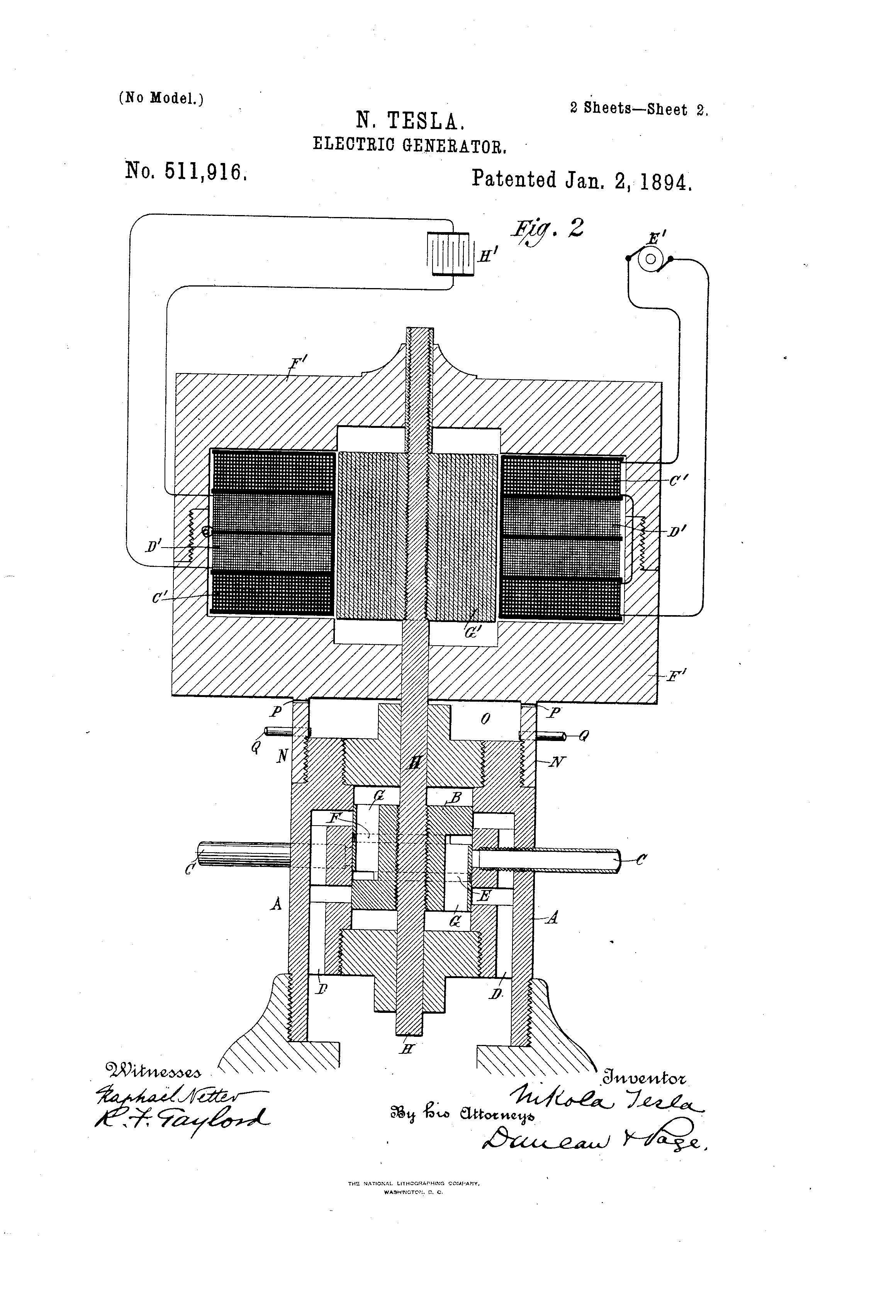
The companion patent, US 511,916, filed the same day, puts a coil of wire on the piston rod and shakes it between the poles of magnets. "The movement of the coil D′ across the lines of force established by the magnets gives rise to alternating currents in the coil. These currents, if the period of mechanical oscillation be constant will be of constant period." Choose 511,916 on the model above to see it.
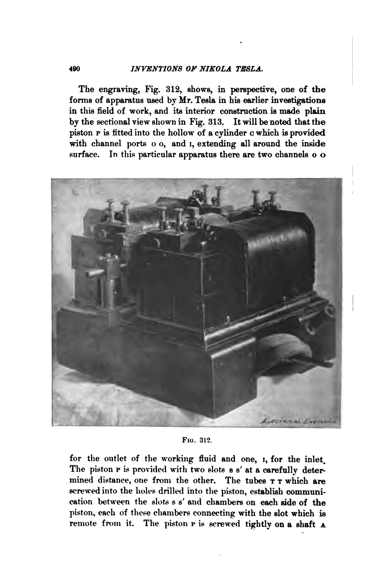
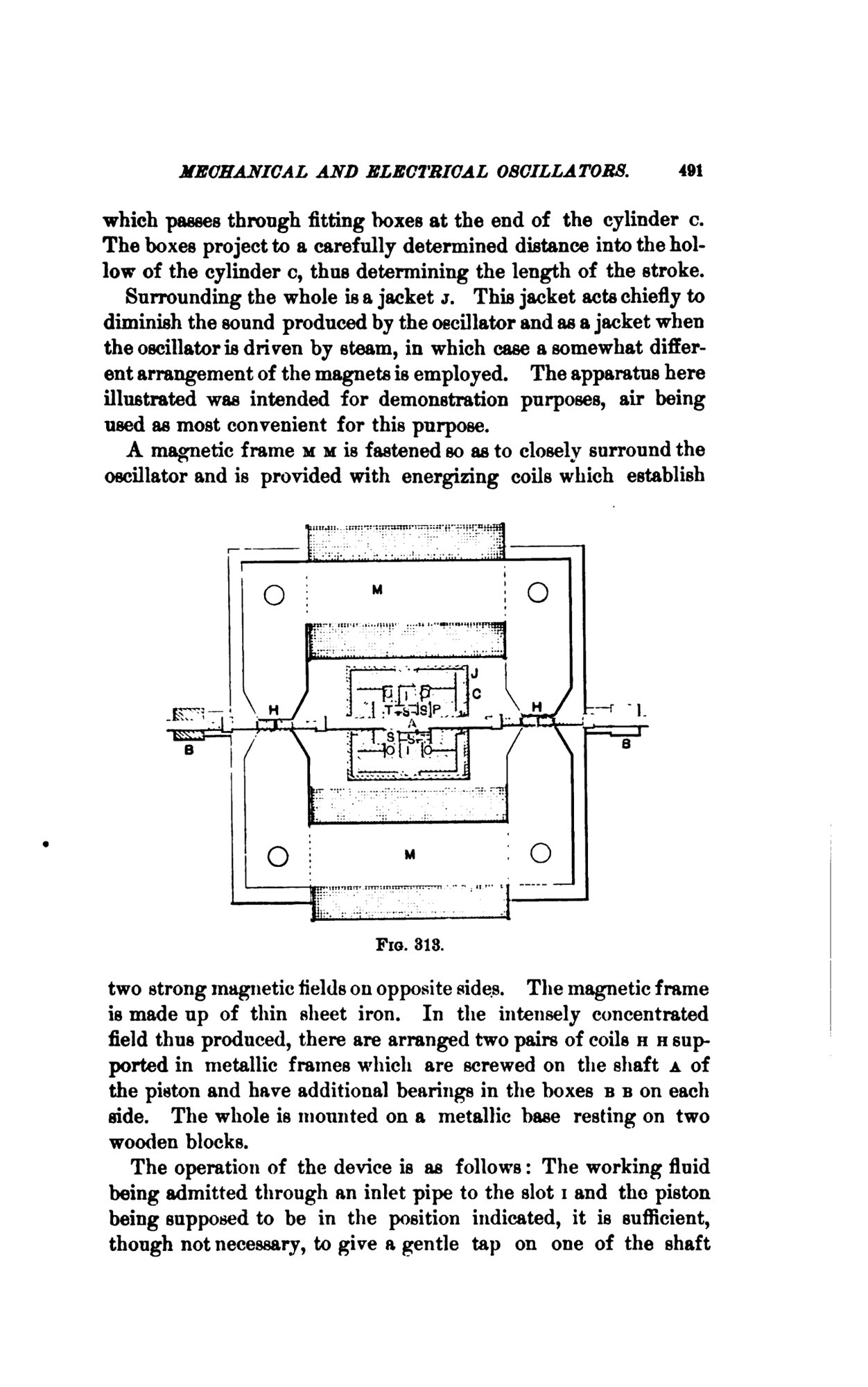
That was the point of the lecture: "owing to the difficulties attending the use of high frequency dynamos", Tesla wanted a machine whose oscillation he could set (The Electrical World). The machines on stage were not built quite like the patent: their pistons bounced on cushions of air in their own cylinders, with coils riding on the shaft between electromagnets (The Electrical Review; Martin, Figs. 312 and 313).
The Electrical World reported compressed air at sixty pounds to the square inch and fifty to ninety strokes a second. According to Martin, one oscillator moved "a weight of approximately 20 pounds at the rate of about 80 per second and with a stroke of about ⅞ inch". A small motor run from one was "greeted by a burst of applause", and Tesla showed "a clock so constructed that it could be attached to one of the oscillators, and would keep absolutely correct time".
The generator patent goes a step further: tune the electric circuit, with a condenser, to the engine's own rate. "It is advantageous that the period of the engine and the natural period of electrical vibration of the generator should be the same, as in such case the best conditions for electrical resonance are established."
Hard questions
The Electrical World's report gives the rates used at the lecture as "from 50 to 90 per second, although from five thousand to ten thousand per second have been obtained". The higher figures are Tesla's statement; the machines on stage ran at fifty to ninety.
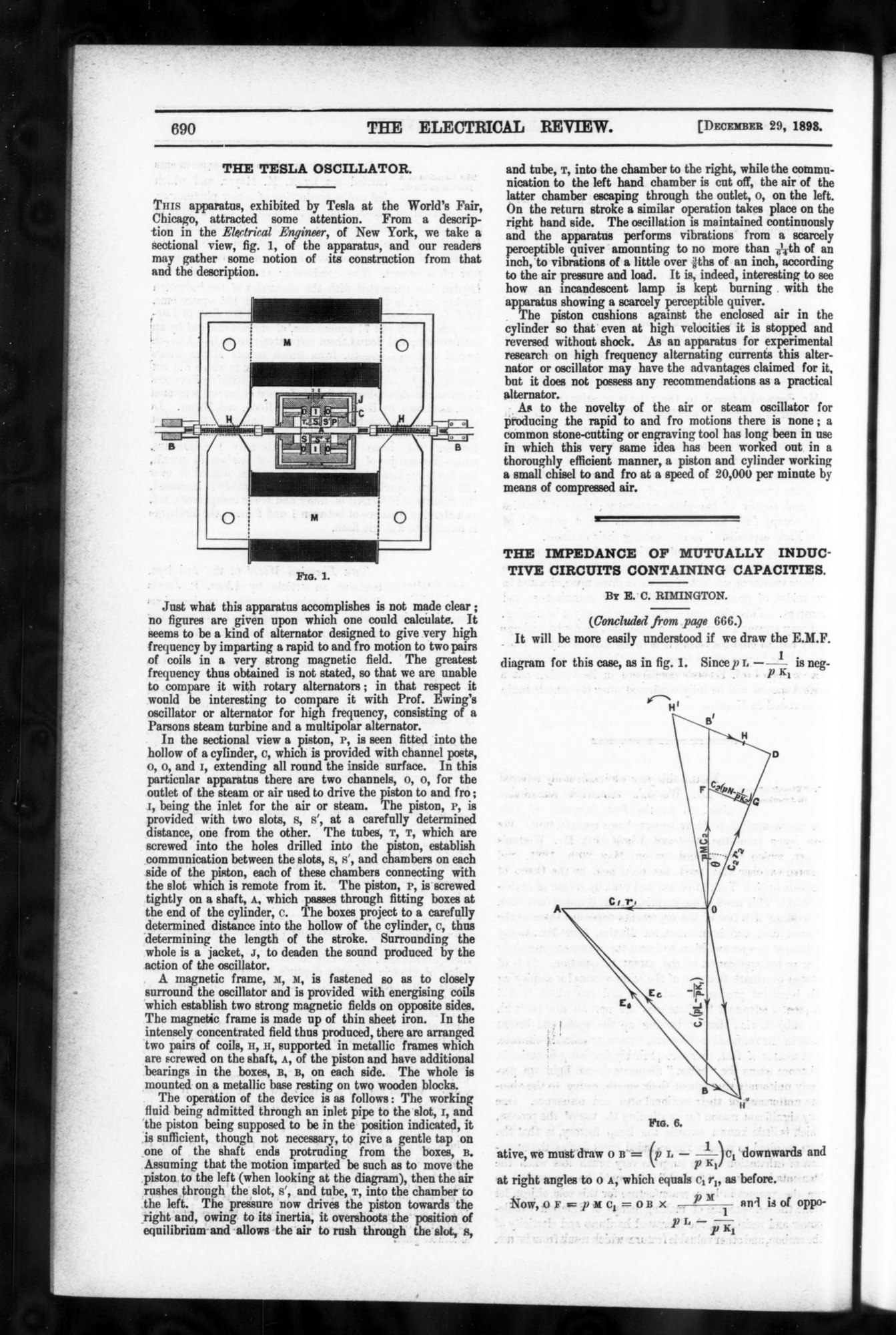
In London, The Electrical Review was not impressed: "Just what this apparatus accomplishes is not made clear; no figures are given upon which one could calculate." The machine "does not possess any recommendations as a practical alternator", it said, and the idea was not new: stone carvers already used "a piston and cylinder working a small chisel to and fro at a speed of 20,000 per minute by means of compressed air".
Even Martin granted that "many inventors, at one time or other, have entertained the idea" of a coil on an engine's piston. What Tesla had added, he argued, was the constant beat, for "the necessity of producing currents of constant period".
What was a constant beat for? Tesla had said so in Chicago: he wanted "to produce electric currents of a perfectly constant period independently of the working conditions", without "spark gaps and breaks" (Martin, p. 486). One use Martin names is tuning: picking out one of several devices on the same wire "by resonance". Picture three telegraph operators sharing one wire, each key sending a hum at its own pitch; at the far end three steel reeds, each tuned to one pitch, each shivering only to its own hum. That only works if the pitches hold still. Martin wrote that "with Mr. Tesla's devices, harmonic and synchronous telegraphy will receive a fresh impetus" (p. 489).
Elisha Gray, who introduced Tesla that evening, had patented harmonic telegraph receivers in 1875 (US 166,094 to 166,096). Alexander Graham Bell had patented tuned reeds on one wire the same year (US 161,739), and his telephone patent of 1876 (US 174,465) begins from it. Bell's application and Gray's caveat for a speaking telegraph reached the Patent Office on the same day, 14 February 1876 (The Telephone Cases, 126 U.S. 1, 1888). A radio does the same sorting today: each station sends on its own frequency and the dial picks one; fibre-optic cables do it with colours of light.
Steam, fire, and no buyers
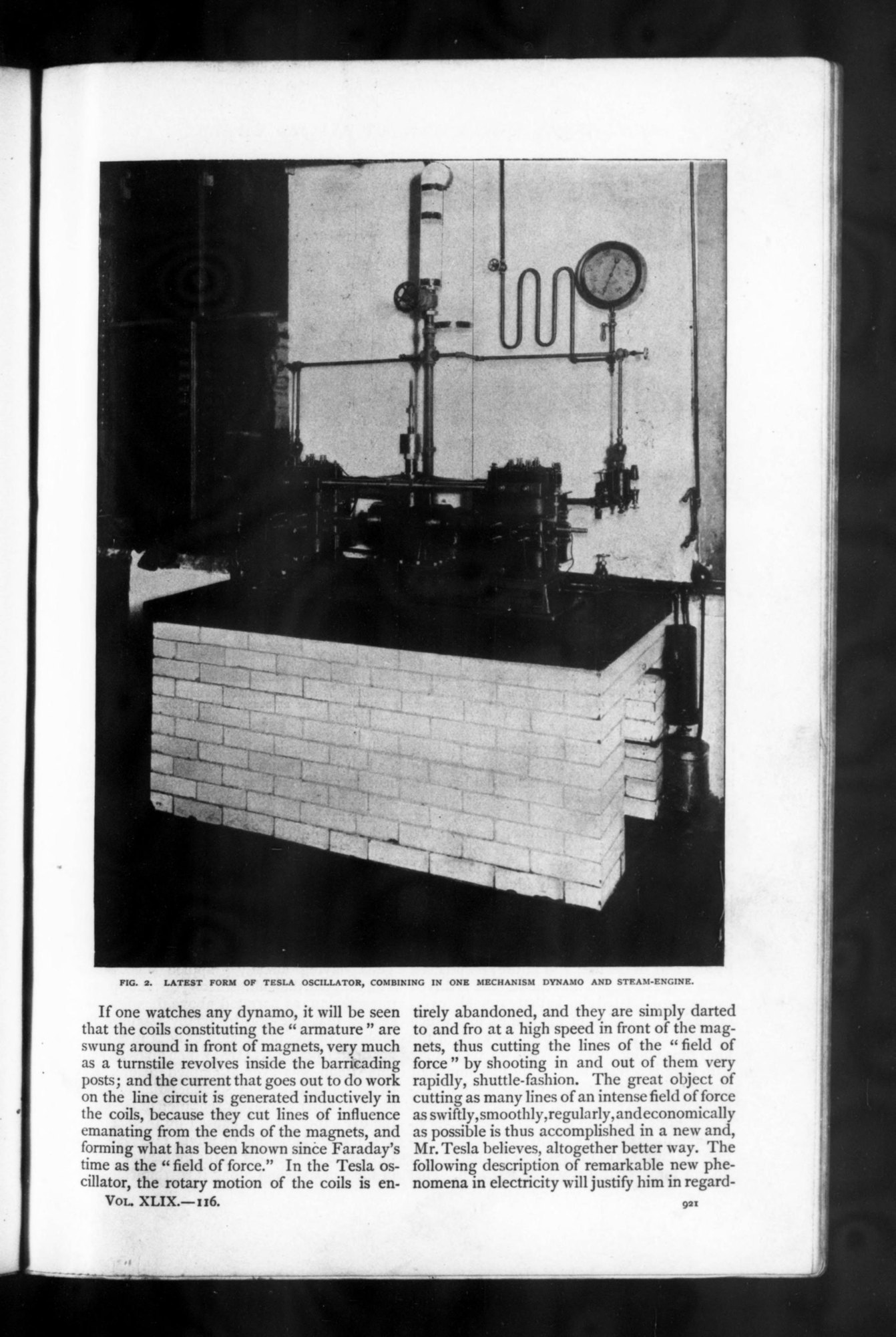
By 1895 there was a steam version, photographed for The Century Magazine "under the special direction of the inventor". Martin's article there said it would make electricity "for half the consumption of steam". It gave no test figures. Martin also wrote, in a digest printed by The Electrical World, that "the most advanced form of the oscillator had been used to light the laboratory for months".
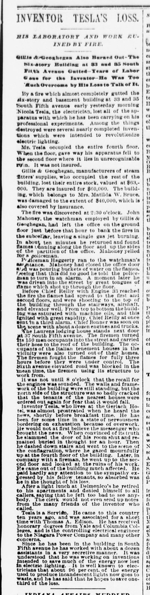
Early on 13 March 1895, fire "almost completely gutted" the building at 33 and 35 South Fifth Avenue, where Tesla had his laboratory. "When the floor gave way his apparatus fell to the second floor", The Sun reported. "It was not insured." The Electrical World listed among the losses "the latest forms of his new type of dynamo, which was approaching commercial completion". That October it added: "The report that the Westinghouse Company has interested itself in the Tesla oscillator is, we learn, unfounded."
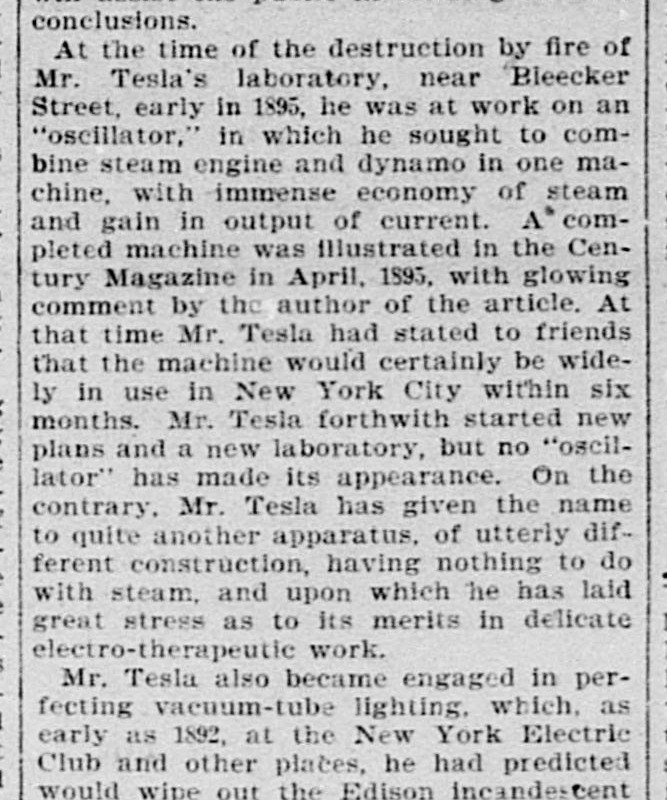
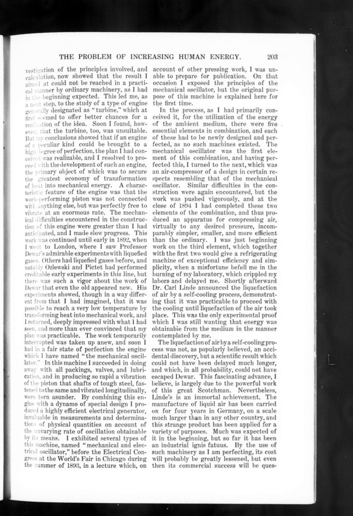
In December 1898 the New York Evening Post went through Tesla's promises. He had told friends, it said, that the machine "would certainly be widely in use in New York City within six months". But "no 'oscillator' has made its appearance", and Tesla had "given the name to quite another apparatus". Tesla's own account came in 1900: the oscillator was the first part of a larger plan, and the fire "crippled my labors and delayed me".
The earthquake machine
The story most people know about this machine is that it nearly brought down a building. It comes from an interview on Tesla's seventy-ninth birthday, in July 1935. The United Press reported that he had "started the Houston-st earthquake of 37 years ago": a "vibration amplifying mechanism set to harmonize with the building's vibrations", fixed to the wall of his laboratory, which he stopped by knocking it off with a hammer (The Washington Daily News, 11 July 1935). A second version of the wire story adds: "Firemen answered alarms to the district. ... It was reported as an earthquake." It says the source was "revealed here for the first time" (The Times-News, Hendersonville, 12 July 1935). The same interview announced a machine to be driven by "cosmic particles".
Nine years later Tesla's biographer, John J. O'Neill, put the story in 1896 and added police officers running over from their headquarters on Mulberry Street. He also wrote that Tesla never told the story beyond that point: "Imagination must finish the finale to the story."
| United Press, 1935 | O'Neill, 1944 | |
|---|---|---|
| Where | his own laboratory building, Houston Street | his Houston Street loft |
| When | "37 years ago": 1898 | 1896 |
| Who came | "Firemen answered alarms" | police from Mulberry Street |
| How it ended | he knocked the gadget off the wall with a hammer | he smashed it with a sledge as the police arrived |
| Told by | Tesla, aged 79, to reporters | his biographer, after Tesla's death |
"It was reported as an earthquake" is something we could check. In October 2026 we searched the Library of Congress's collection of digitised newspapers, Chronicling America, and read every result where the words fall near each other:
| Searched | Years | Pages | A report of a tremor, panic or alarm at Tesla's laboratory? |
|---|---|---|---|
| "tesla earthquake" | 1894–1900 | 189 | No |
| "tesla vibration" | 1894–1900 | 389 of 447 | No |
| "tesla oscillator" | 1893–1900 | 279 of 291 | No |
| "houston street earthquake", New York papers | 1895–1899 | 84 | No |
| The Electrical World, every weekly issue | 1894–1898 | 262 issues | No |
| The Electrical World and The Electrical Review (London) | July–December 1893 | No | |
| The Associated Press report of the same 1935 interview (Evening Star, Washington, read on the page) | 1935 | No earthquake | |
| Tesla, "My Inventions" (machine reading of all six parts) | 1919 | Not found |
Not searched: The New York Times, the New York Herald and the Brooklyn Eagle, which are not in that collection, and The Electrical Engineer for 1896 to 1899. A report in one of those would change the answer. In the newspapers we searched, there is none. The hostile review of December 1898, written in the year the 1935 story points to, says nothing about it either.
What the record from the 1890s does show is vibrating machines. In Chicago, Martin saw "the pieces of a steel arbor which had been actually torn apart while vibrating against a minute air cushion". In January 1896 The Journal of New York reported that Tesla had an apparatus for curing disease: "The cures will be effected by means of a thorough shaking up of the human system. Mr. Tesla calls the treatment a system of mechanical vibrations, and his apparatus he calls an oscillator." Its story: "Ex-Mayor Abram S. Hewitt recently visited Tesla's new laboratory in East Houston street, and complained that he was troubled with his liver." Tesla sat him in a chair with a newspaper and went out, "in reality to turn on the electric current. When he returned, in a minute or so, Mr. Hewitt seemed an entirly changed man" (the paper's spelling). And in 1900 Tesla wrote of "so rapid a vibration of the piston that shafts of tough steel, fastened to the same and vibrated longitudinally, were torn asunder". Small pushes, well timed, can build a big swing. Whether one of his machines ever shook a building, no one we found said so at the time. The shaking we did find on Houston Street was a chair, with a former mayor in it.
1916: a valve with nothing inside that moves
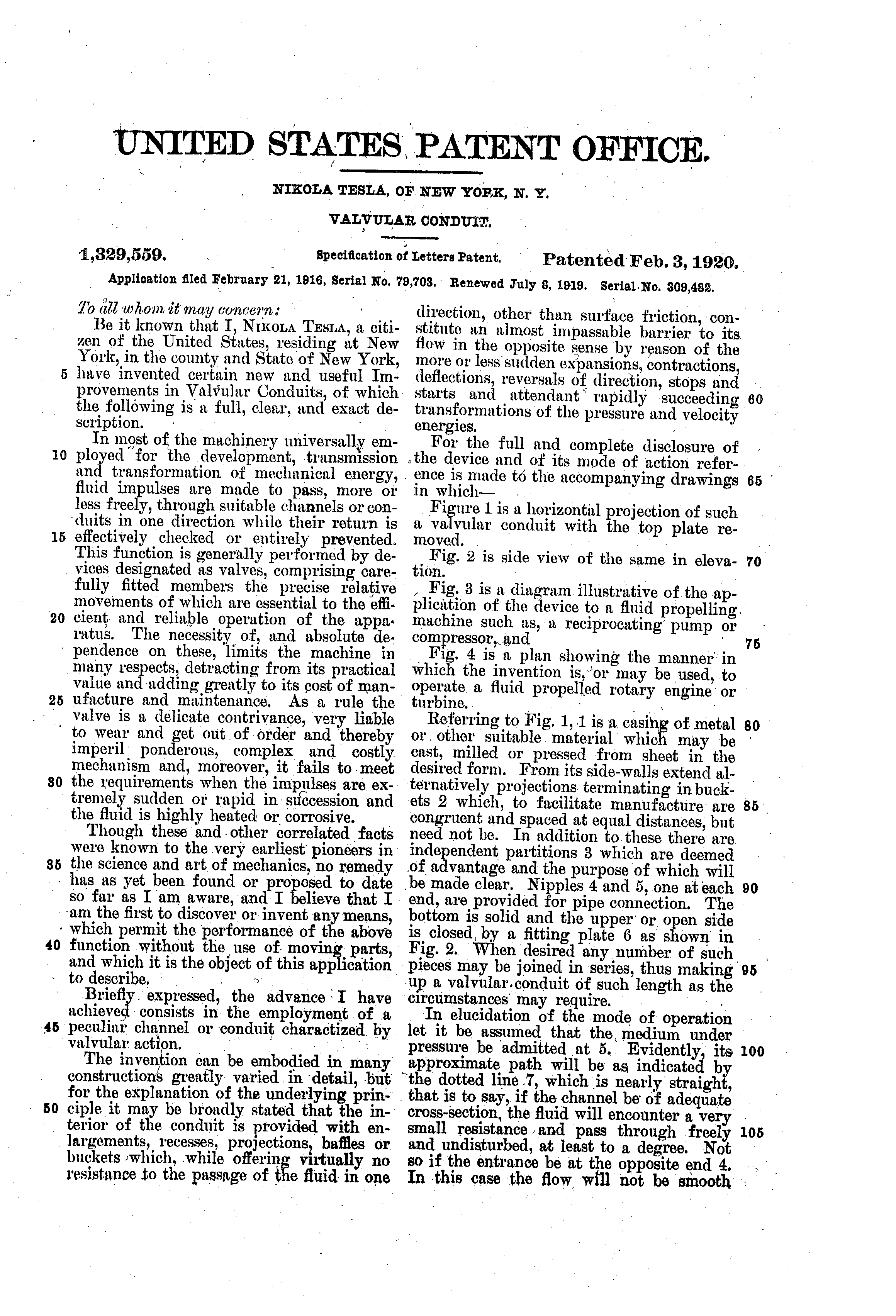
In that article of 1900, Tesla wrote that in his oscillator he had succeeded "in doing away with all packings, valves, and lubrication". On 21 February 1916 he applied for a patent on a way to do without valves altogether. It was granted on 3 February 1920 as US 1,329,559, Valvular Conduit.
Valves, he wrote, are "a delicate contrivance, very liable to wear and get out of order", and they fail "when the impulses are extremely sudden or rapid in succession and the fluid is highly heated or corrosive". His answer is a channel with "enlargements, recesses, projections, baffles or buckets which, while offering virtually no resistance to the passage of the fluid in one direction, other than surface friction, constitute an almost impassable barrier to its flow in the opposite sense".
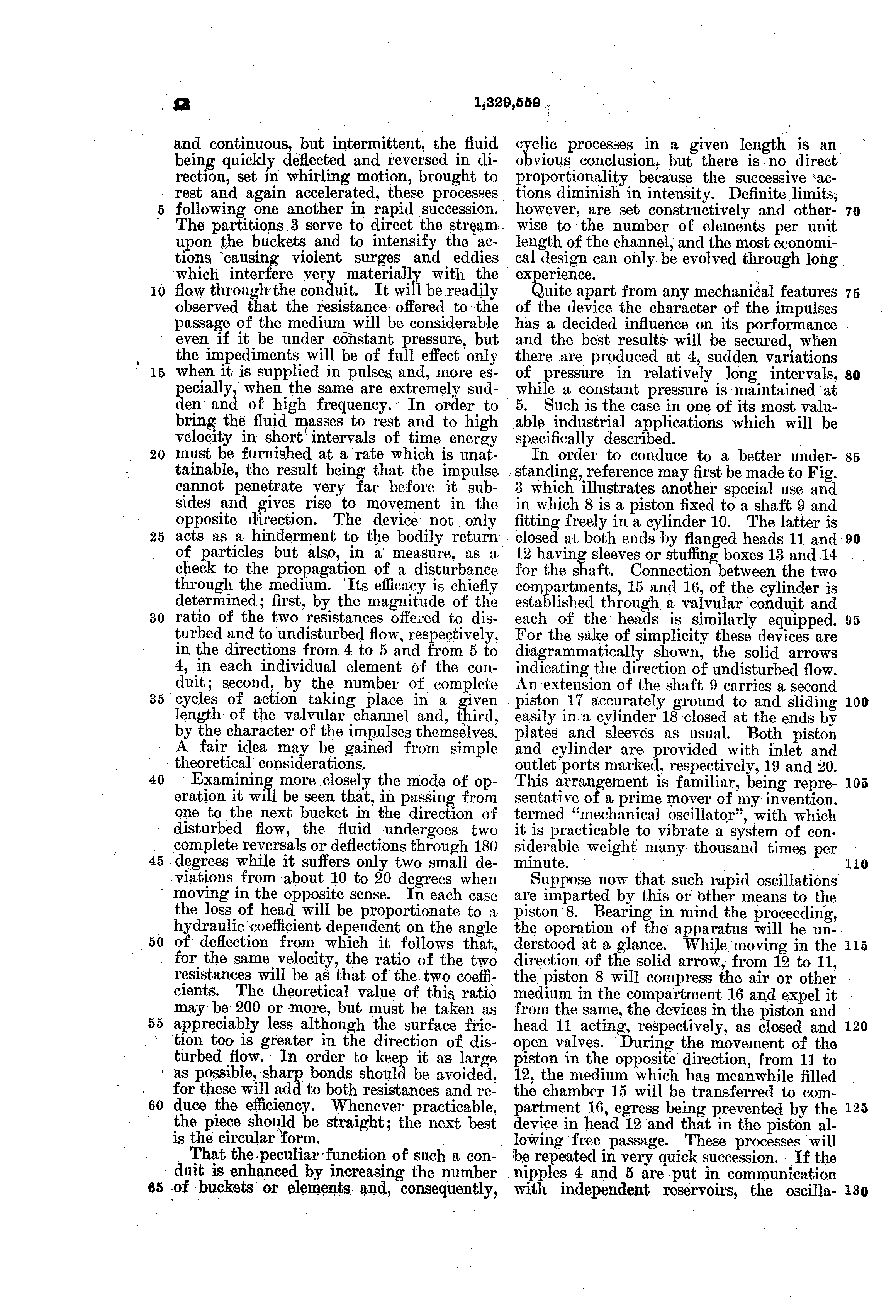
Fig. 1 is a flat casing 1 with hooked pockets, the buckets 2, on alternate sides, and an island, a partition 3, in front of each one: eleven in all, by our count of the drawing. Let the fluid in at the end marked 5 and it runs almost straight through, along the dotted line 7, with "only two small deviations from about 10 to 20 degrees" at each element. Let it in at 4 and it meets "two complete reversals or deflections through 180 degrees" at each one. In theory, he wrote, the resistance one way could be "200 or more" times the other, "but must be taken as appreciably less".
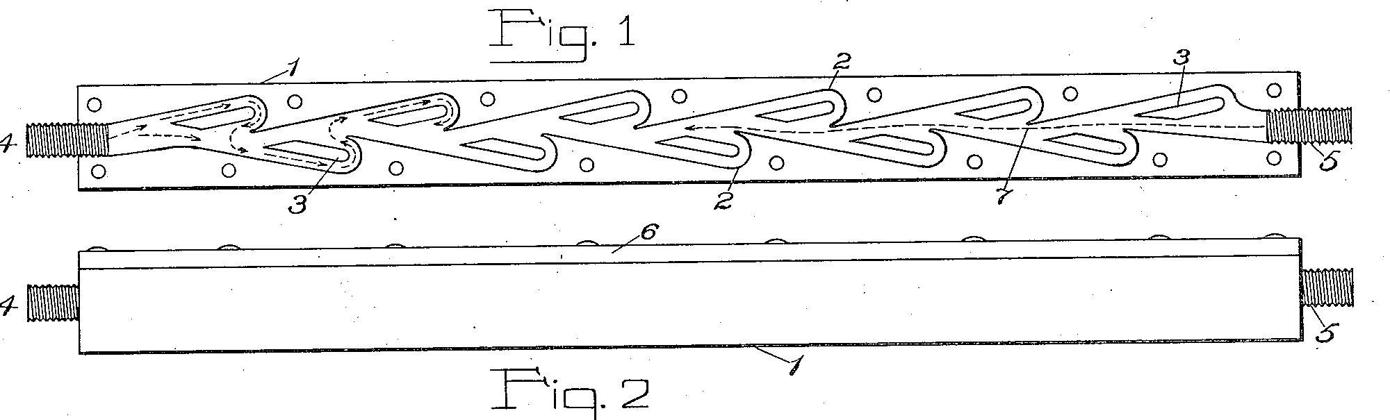
From the patent: the casing 1, the buckets 2, the eleven partitions 3, the nipples 4 and 5, the top plate 6 bolted on (Fig. 2), and the dotted line 7. Every outline is traced off the scan of Fig. 1, with the scan's tilt of 0.6° taken out; by our measurement the partitions lean 8 to 9½° to the axis, alternately one way and the other. Ours: the depth of the channel and of the casing, the top plate's thickness, the nipples and the bolt heads (the patent gives no dimensions).
Our simulation: one way, then the other
We ran Fig. 1 through a flow simulation of our own: water in two dimensions, in the channel traced from the drawing, computed by the lattice Boltzmann method. Two lines of dye are let in at the inlet, and the water is pale blue where it moves fast. This is our work, at our own Reynolds number of about 400 (a measure of how far the water's momentum wins over its stickiness). It is not the 2021 experiment described below, and none of its numbers is theirs.
Our simulation (lattice Boltzmann, D2Q9, on a grid 40 cells across the channel's mean width; walls traced from Fig. 1; a straight duct at each end; the flow rate set at the inlet). In the two steady runs the dye goes in at the end the water enters. "Pushed back and forth": the pressure at 5 swings above and below the pressure at 4, with no steady push either way; the dots are tracer particles, the chart is the flow through the middle of the channel, and the tally is the net amount of water that has gone forward, as a share of the channel's volume. A control run, the same drive on the channel turned end for end, sent the net flow the other way, so the forward drift comes from the channel's shape and not from the way we drove it. What our runs measured, in two dimensions and in our units (ours, not the paper's): the pressure needed to push water in at 4 was about the same as at 5 at our Reynolds number of 50, and about 1.7 times as much at 400. The recording plays at its own pace; the water's speed in it is not to scale with any real valve.
Pulses in, flow out
The conduit, Tesla wrote, is "of full effect only when it is supplied in pulses and, more especially, when the same are extremely sudden and of high frequency". He granted that "asymmetrical conduits have been constructed and their use proposed in connection with engines", with pockets that turned the flow only part of the way, for "slowly reciprocating machines". His claim was the full turn, and speed.
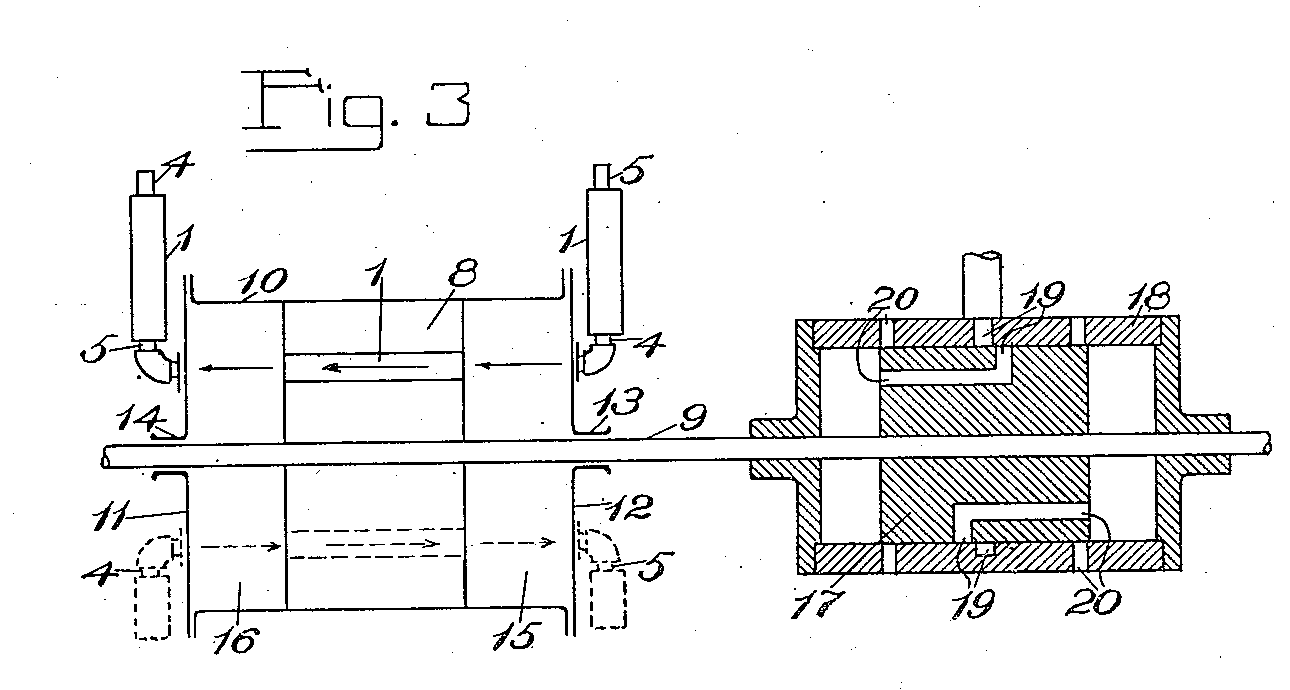
So the same drawing sheet shows the oscillator again. Fig. 3 is a pump whose piston is shaken by "a prime mover of my invention termed 'mechanical oscillator', with which it is practicable to vibrate a system of considerable weight many thousand times per minute". Valvular conduits in the piston and in each end of the cylinder let air through one way only, so the shaking becomes "a compression of the air at 4 and rarefaction of the same at 5". Turn the conduits round and it pumps the other way.
Fig. 4 is his disk turbine, from episode 8, fired by explosions. Gas and air burn in a small chamber above the disks. "Both the conduits behaving, with respect to efflux, as closed valves, the products of combustion rush out through the nozzle 29" onto the disks, and the suction that follows draws in fresh air and gas through the conduits, the easy way. There is "no compressor, buckets or troublesome valve mechanism", and the pulses "may, under certain conditions, reach hundreds and even thousands per second".
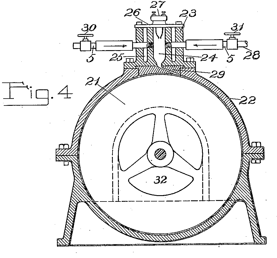
He wrote that he did not claim these machines in this patent, "as these will be made subjects of separate applications". We found no such patent among his later grants. The 2021 paper below says that "it is unclear if Tesla ever fabricated and tested a prototype", and we found no report that he built either machine, or the valve itself.
A century later, at NYU
In 2021 Quynh Nguyen, Joanna Abouezzi and Leif Ristroph of New York University's Applied Math Lab published a test of the valve, made "faithful to Tesla's original design": a channel digitised from his Fig. 1, thirty centimetres long, cut in clear acrylic. They ran water through it both ways and measured the resistance.
"For low Re, Di is close to unity": when the flow was slow, the channel was no valve at all. Then, "over a narrow transitional range Re = 100-300, the diodic function of the channel abruptly 'turns on'", and from 300 to 1,500 the resistance in reverse was about twice that forward. Twice, not two hundred: "the diodicity value of 200 stated in Tesla's patent seems well beyond reach, at least for the fluid dynamical regime studied here." Their dye shows why: forward, the threads stay in the middle; in reverse they ricochet off the islands into the pockets and mix.
Then they tested his other idea, pulses. Four conduits round a piston shaken back and forth, connected like an electrical rectifier, sent water round one way, and the pumping was "as high as B ≈ 2.5 and thus more than a doubling" of what their steady measurements predicted, best with small, fast strokes. In their words: "Our results confirm Tesla's conjecture that diodic performance is boosted for pulsatile flows."
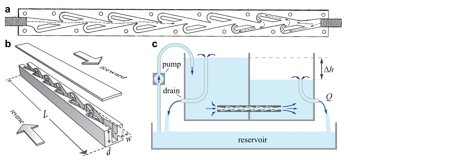
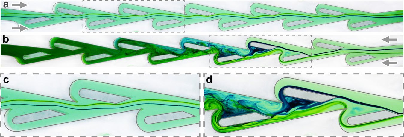
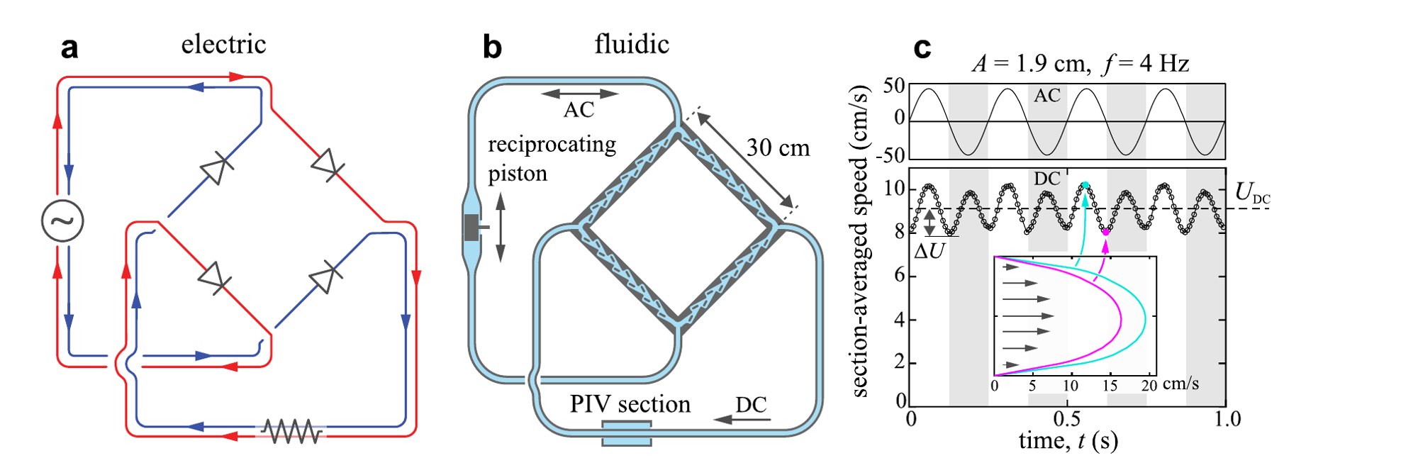
Figures from Q. M. Nguyen, J. Abouezzi and L. Ristroph, "Early turbulence and pulsatile flows enhance diodicity of Tesla's macrofluidic valve", Nature Communications 12, 2884 (2021), doi:10.1038/s41467-021-23009-y, licensed CC BY 4.0; cropped.
What held up
An engine that kept time, shown on stage in Chicago in 1893, and a valve that really does favour one direction, more so when it is pulsed. What did not: two hundred to one, and an earthquake that no newspaper we searched reported.
Tesla never sold his engine, and never saw his valve tested. He died in January 1943 at the Hotel New Yorker, aged 86 (Associated Press, Evening Star, 8 January 1943). The steady beat he wanted is in every wall socket: the grid alternates sixty times a second in North America and fifty in most other places, held so steady that synchronous electric clocks kept time by it, from the Telechron of 1919 until other clocks displaced them from 1969 (NERC). Why sixty and fifty? Westinghouse's Benjamin Lamme wrote in 1918 that sixty came out of L. B. Stillwell's study, about 1890, of the engine speeds then in sight: "7200 alternations per minute (60 cycles per second), was about as high as would be desirable". Transformers would have liked it higher and the engines lower; sixty was the compromise. It was not chosen to bring forward Tesla's motor, whose development Westinghouse had laid aside in 1890. Fifty, Lamme wrote, "has become the standard high frequency of Europe"; we found no record of why it was chosen there. And since 1960 magnetic flux density has been measured in teslas (BIPM, 11th CGPM, Resolution 12).
Read the original patents
All three patents are in the public domain. Click a page for full resolution; drawing sheets come first, then the specification.
US 514,169, Nikola Tesla, Reciprocating Engine, filed 19 August 1893, granted 6 February 1894
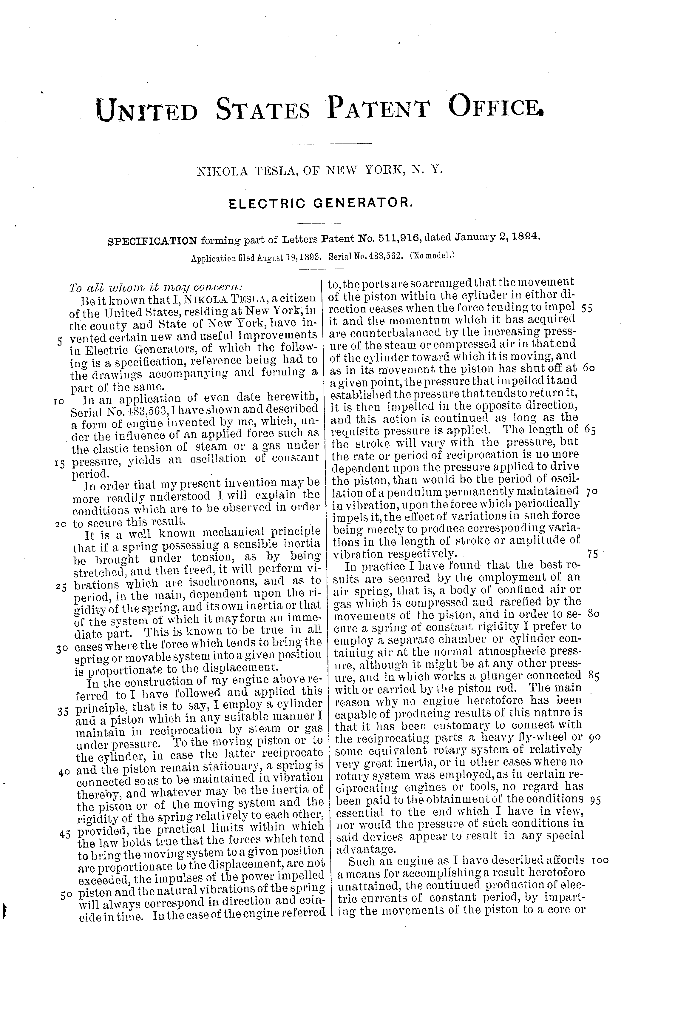
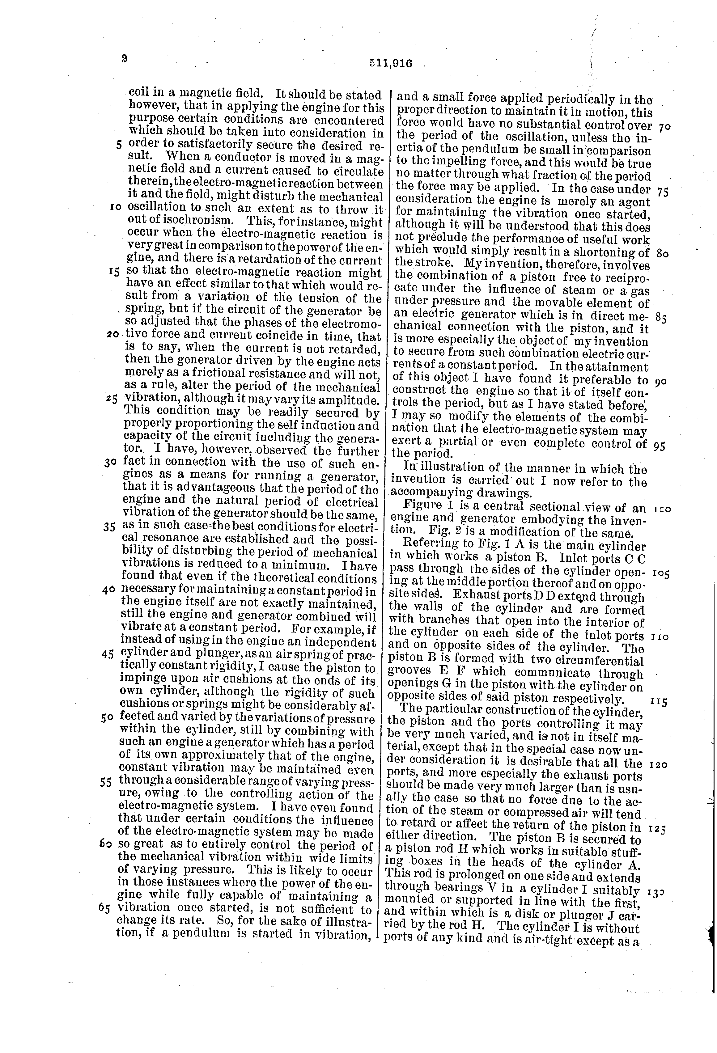
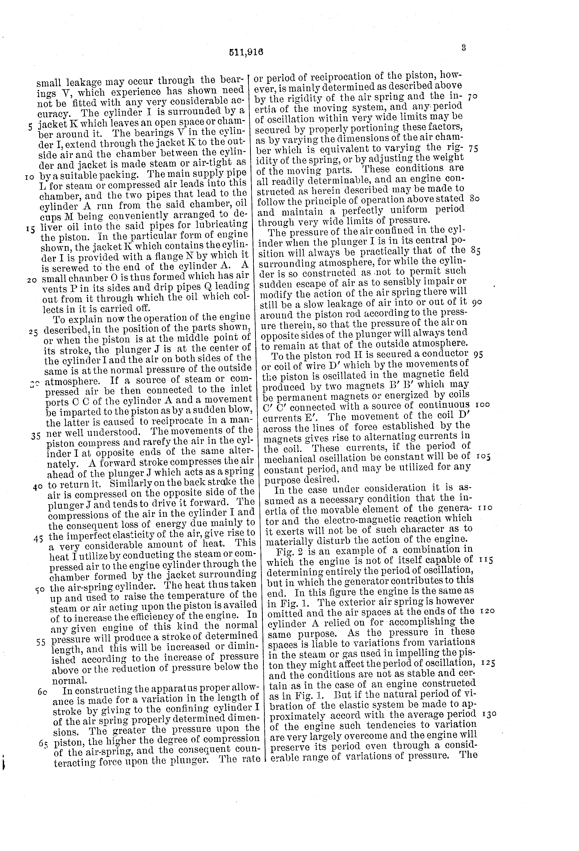
US 511,916, Nikola Tesla, Electric Generator, filed 19 August 1893, granted 2 January 1894
US 1,329,559, Nikola Tesla, Valvular Conduit, filed 21 February 1916, renewed 8 July 1919, granted 3 February 1920
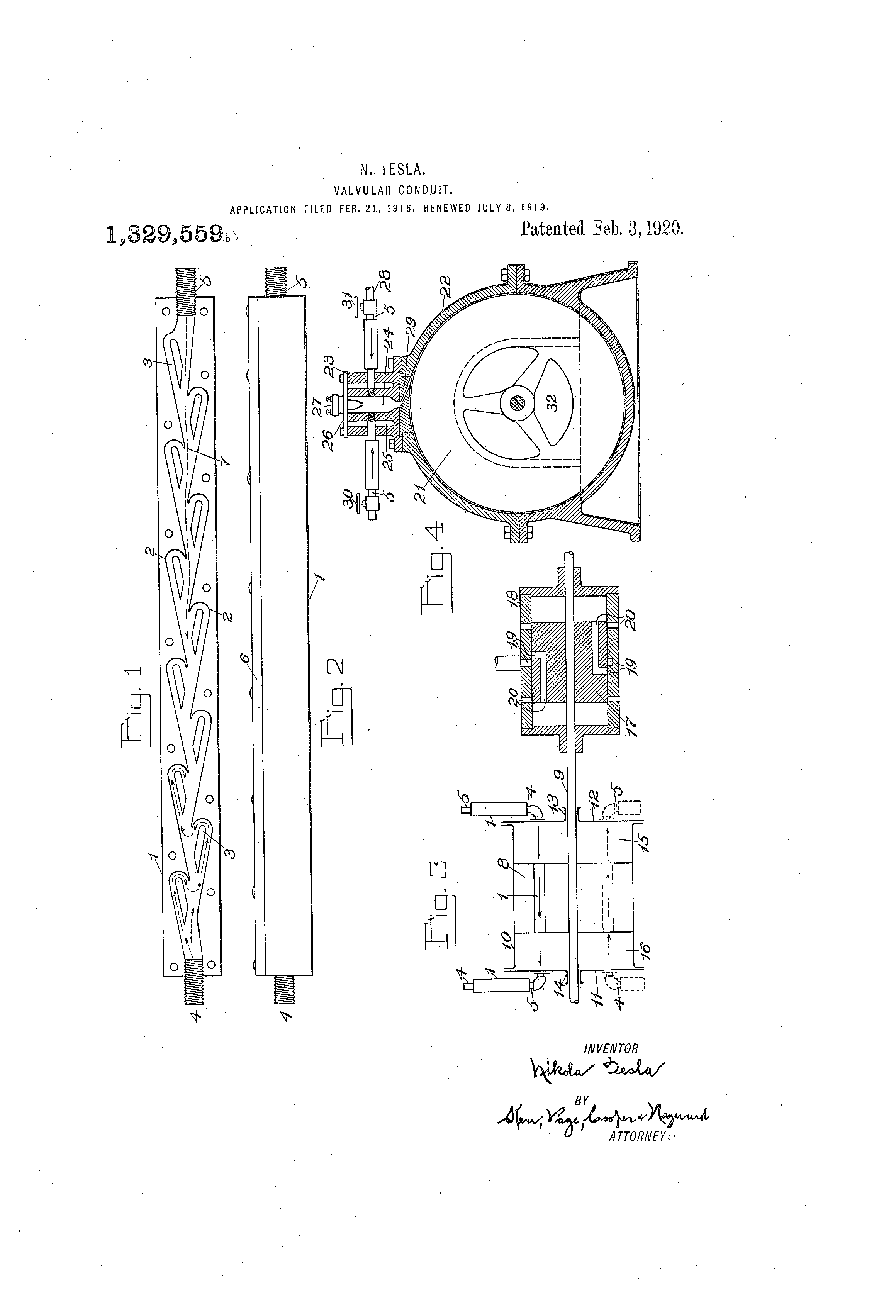
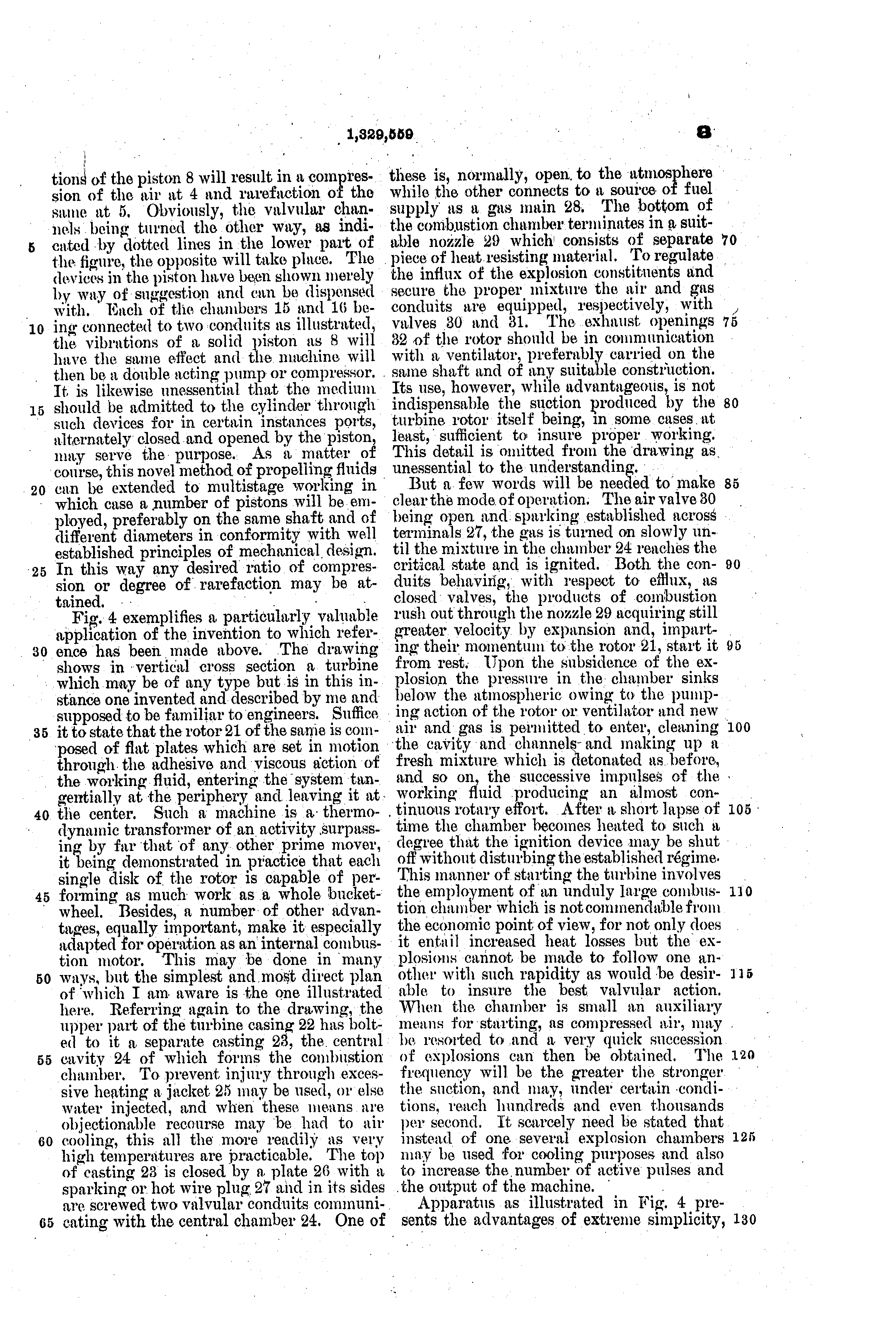
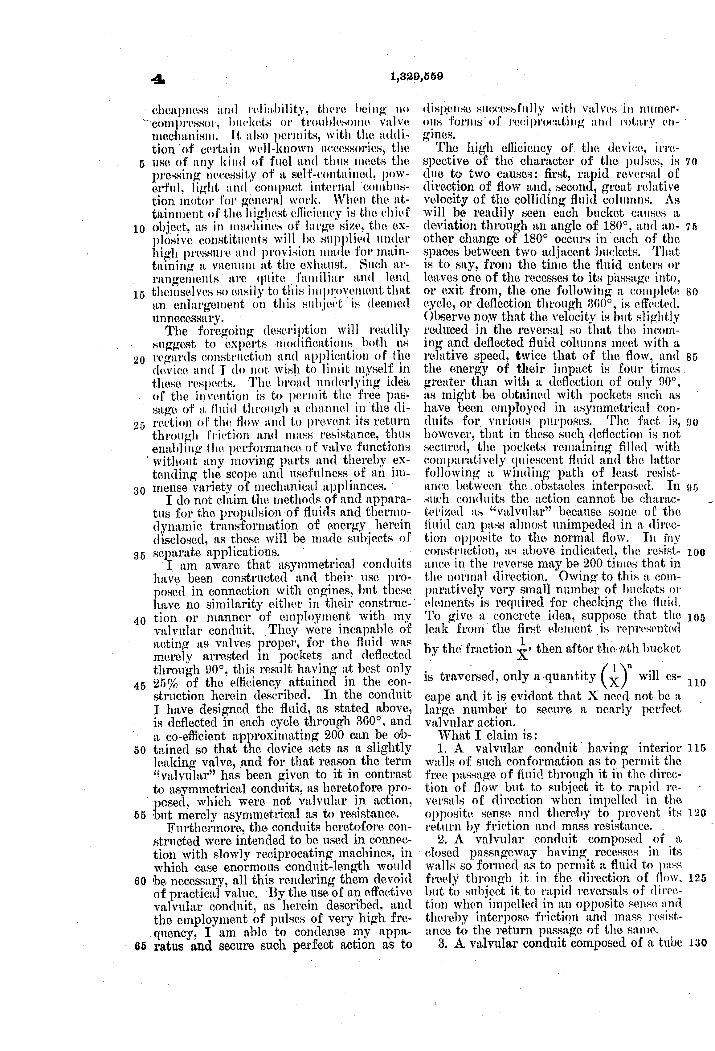
PDF · Google Patents · Figs. 1 and 2, Fig. 3 and Fig. 4, turned upright.
Sources
Every fact on this page comes from these, as in the episode. Where we have read a source only second-hand, or only as a machine reading of the page, the text says so.
Patents
- N. Tesla, Reciprocating Engine, US Patent 514,169, filed 19 August 1893, granted 6 February 1894: the flywheel, the ports, "a sudden blow", the air spring and the coiled-spring picture, the pendulum sentence, changing the rate, the train of a clock.
- N. Tesla, Electric Generator, US Patent 511,916, filed 19 August 1893, granted 2 January 1894: coil D′ between magnets B′, currents "of constant period", "the best conditions for electrical resonance".
- N. Tesla, Valvular Conduit, US Patent 1,329,559, filed 21 February 1916, granted 3 February 1920: the trouble with valves, the buckets and partitions, the deviations and reversals, "200 or more", the pulses, earlier asymmetrical conduits, the pump of Fig. 3 and the turbine of Fig. 4, "separate applications".
History
- T. C. Martin, The Inventions, Researches and Writings of Nikola Tesla (New York: The Electrical Engineer, 1894), chapters XLII–XLIII, pp. 477–493, Figs. 297, 312 and 313: the exhibit, the lecture of 25 August 1893, the air compressor, the torn steel arbor, 20 pounds at 80 a second, the clock, "many inventors".
- Official Catalogue, Part X, Department J, Electricity (Chicago: W. B. Conkey, 1893), p. 27, entry 429a (Westinghouse, space B-1).
- Proceedings of the International Electrical Congress, Chicago, August 1893 (New York: American Institute of Electrical Engineers, 1894), p. 485: the final general meeting, Friday 25 August, and the announcement of the lecture at eight.
- J. P. Barrett, Electricity at the Columbian Exposition (Chicago: R. R. Donnelley, 1894), pp. 168–169: Tesla's room in a Westinghouse space, and the oscillators shown outside it. (Barrett says the lecture was to the American Institute of Electrical Engineers; the Congress's Proceedings record it as the Congress's.)
- "The Tesla Lecture" (p. 167) and "Tesla's Lecture on Mechanical and Electrical Oscillators" (pp. 175–176), The Electrical World 22:10, 2 September 1893: the audience, "un-Teslean", "a disappointment", "high frequency dynamos", sixty pounds, fifty to ninety a second, the applause.
- "The Tesla Oscillator", The Electrical Review (London) 33, 29 December 1893, p. 690: the stage machine in section and the verdict.
- T. C. Martin, "Tesla's Oscillator and Other Inventions", The Century Magazine 49:6, April 1895, pp. 916–933: the steam oscillator, "under the special direction of the inventor", "for half the consumption of steam".
- "Inventor Tesla's Loss", The Sun (New York), 14 March 1895, p. 5: the fire.
- The Electrical World 25:12, 23 March 1895 ("Tesla's Loss": "the latest forms of his new type of dynamo"); 25:14, 6 April 1895 (a digest of Martin in The Engineering Magazine: the laboratory lit for months; we have read the digest only); 26:15, 12 October 1895 (Westinghouse, "unfounded"). Read in the Internet Archive's machine reading of the scans.
- "Electric Sensationalism: Tesla's Promises and Performances", from the New York Evening Post, in The Times (Washington), 27 December 1898, p. 2.
- N. Tesla, "The Problem of Increasing Human Energy", The Century Magazine 60:2, June 1900, p. 203: "doing away with all packings, valves, and lubrication", "shafts of tough steel", "crippled my labors and delayed me".
- N. Tesla, "My Inventions", The Electrical Experimenter, February–June and October 1919: searched in a machine reading for the earthquake, the mechanical oscillator, resonance and steel; not found (a machine reading can miss words).
- Wire story of January 1896 on Tesla's "system of mechanical vibrations", Sacramento Record-Union, 17 January 1896, p. 4 (read in the Library of Congress's machine reading of the page).
- "May Cure Even Consumption", The Journal (New York), 16 January 1896, p. 3: the oscillator cure, Hewitt in the chair, "Tesla's new laboratory in East Houston street". Read on the page image.
- Associated Press, "Giant Discoveries Claimed by Tesla", Evening Star (Washington), 11 July 1935, p. 14: the same birthday interview, three claims, no earthquake. United Press, "Noted Inventor Uses Birthday to Reveal 'Earthquake Maker'", Imperial Valley Press, 11 July 1935, p. 2. Both read on the page images.
- Associated Press, "Nikola Tesla Dies", Evening Star (Washington), 8 January 1943: aged 86, at the Hotel New Yorker (read in the Library of Congress's machine reading of the page).
- G. B. Prescott, Electricity and the Electric Telegraph, 7th ed., vol. 2 (New York: Appleton, 1888), pp. 1090-1096: Gray's harmonic telegraph. E. Gray, US Patents 166,094, 166,095 and 166,096 (27 July 1875); A. G. Bell, US Patents 161,739 (6 April 1875) and 174,465 (7 March 1876); The Telephone Cases, 126 U.S. 1 (1888): "afterwards, during the same day".
- NERC, BAL-004-0 white paper on time error correction (2015), p. 2: Warren's synchronous motor (1916), the Telechron clock (1919), electric clocks displaced from 1969. BIPM, 11th General Conference on Weights and Measures (1960), Resolution 12: the tesla.
- B. G. Lamme, "The Technical Story of the Frequencies", Transactions of the American Institute of Electrical Engineers 37 (1918), pp. 66-71: 133⅓ cycles, Stillwell's study and 60 cycles (p. 67), not chosen for the induction motor and the Tesla motor work laid aside in 1890 (p. 68), 50 cycles in Europe (p. 71).
- United Press, "Scientist Admits Starting Quake 37 Years Ago", The Washington Daily News, 11 July 1935, p. 31; "Tesla Admits He Produced 'Earth Quake'", The Times-News (Hendersonville, N.C.), 12 July 1935, p. 6. Both read on the page images.
- J. J. O'Neill, Prodigal Genius: The Life of Nikola Tesla (New York: Ives Washburn, 1944), the earthquake chapter: 1896, Mulberry Street, "Imagination must finish the finale to the story". Read in an online copy.
- Library of Congress, Chronicling America: our searches of October 2026, as listed in the table above.
- Q. M. Nguyen, J. Abouezzi and L. Ristroph, "Early turbulence and pulsatile flows enhance diodicity of Tesla's macrofluidic valve", Nature Communications 12, 2884 (2021), CC BY 4.0: the conduit and its test, the transition at Re 100–300, a diodicity of about 2, "well beyond reach", the pump of four conduits, "as high as B ≈ 2.5", "it is unclear if Tesla ever fabricated and tested a prototype".
- "List of Nikola Tesla patents", Wikipedia, read 14 October 2026: his US grants after 1920, where we found no patent for the machines of Figs. 3 and 4.
- Our flow simulation (lattice Boltzmann, two dimensions) and the reconstructions are our own work, as described under each model.
Images
- Patent drawings and specifications: USPTO, public domain.
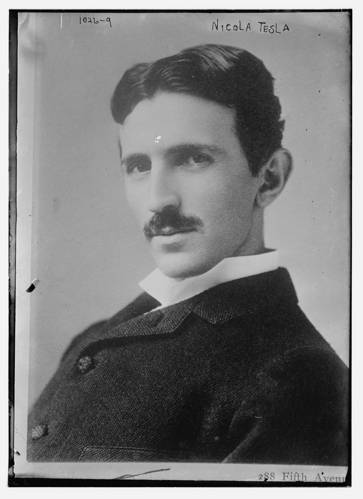
- Nikola Tesla, about 1890, photograph by Napoleon Sarony: Library of Congress, Prints & Photographs Division, Bain Collection, LCCN 2014684845, no known restrictions on publication.
- C. D. Arnold, Official Views of the World's Columbian Exposition (1893), plate 29, via Wikimedia Commons: public domain.
- Martin (1894), The Electrical World (1893), The Electrical Review (1893), The Century Magazine (1895, 1900), the Official Catalogue (1893), the Congress's Proceedings (1894) and Barrett (1894): published before 1931, public domain; scans via the Internet Archive.
- The Sun (1895) and The Times (1898): Library of Congress, Chronicling America; public domain.
- Figures 1, 3 and 5 of Nguyen, Abouezzi and Ristroph (2021): CC BY 4.0, cropped.
