 Curious Patents
Try to make it run
The Patent Office granted the same impossible wheel twice, a hundred and seven years apart. Here are the machines from the episode. Push them, change them, and watch where the energy goes.
Watch the episode
The rule every one of them breaks
Energy is never made or destroyed, only moved from one form to another. A wheel that turns itself would have to make energy from nothing, so each of these machines is either quietly taking energy back as fast as gravity gives it, or getting it from somewhere hidden. Each model below keeps a ledger, so you can see which.
Rutkove's gravity wheel, 1971
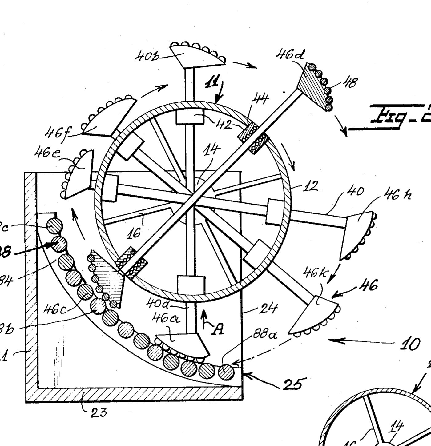
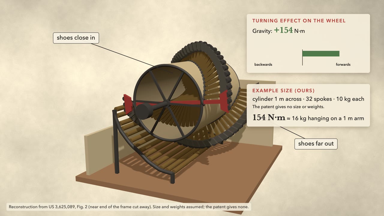
In 1971 the Patent Office granted Edward Rutkove, of Brooklyn, US Patent 3,625,089 for a "Gravity Wheel Apparatus". Weighted shoes on the ends of spokes slide through a cylinder, and a curved ramp of rollers underneath pushes each spoke across as it comes round, so the shoes on the right stay far out and the shoes on the left stay close in. His wheel has a motor, but only, he wrote, "to overcome inertia" and "occasionally to overcome residual friction".
Push it. The gravity bar is forward the whole way round, just as the patent says. The ramp's bar is always backward, because to keep the right side long, the ramp has to lift every spoke as it passes the bottom.
The ramp, the spokes and their travel are measured off Rutkove's Figure 2; the size, the weights and the cylinder's own weight (40 kg) are ours. Without friction the wheel keeps whatever speed you give it and never speeds itself up. With friction it slows to a stop, unless the motor runs, and then the battery pays for every turn.
Greene's wheel, 1864
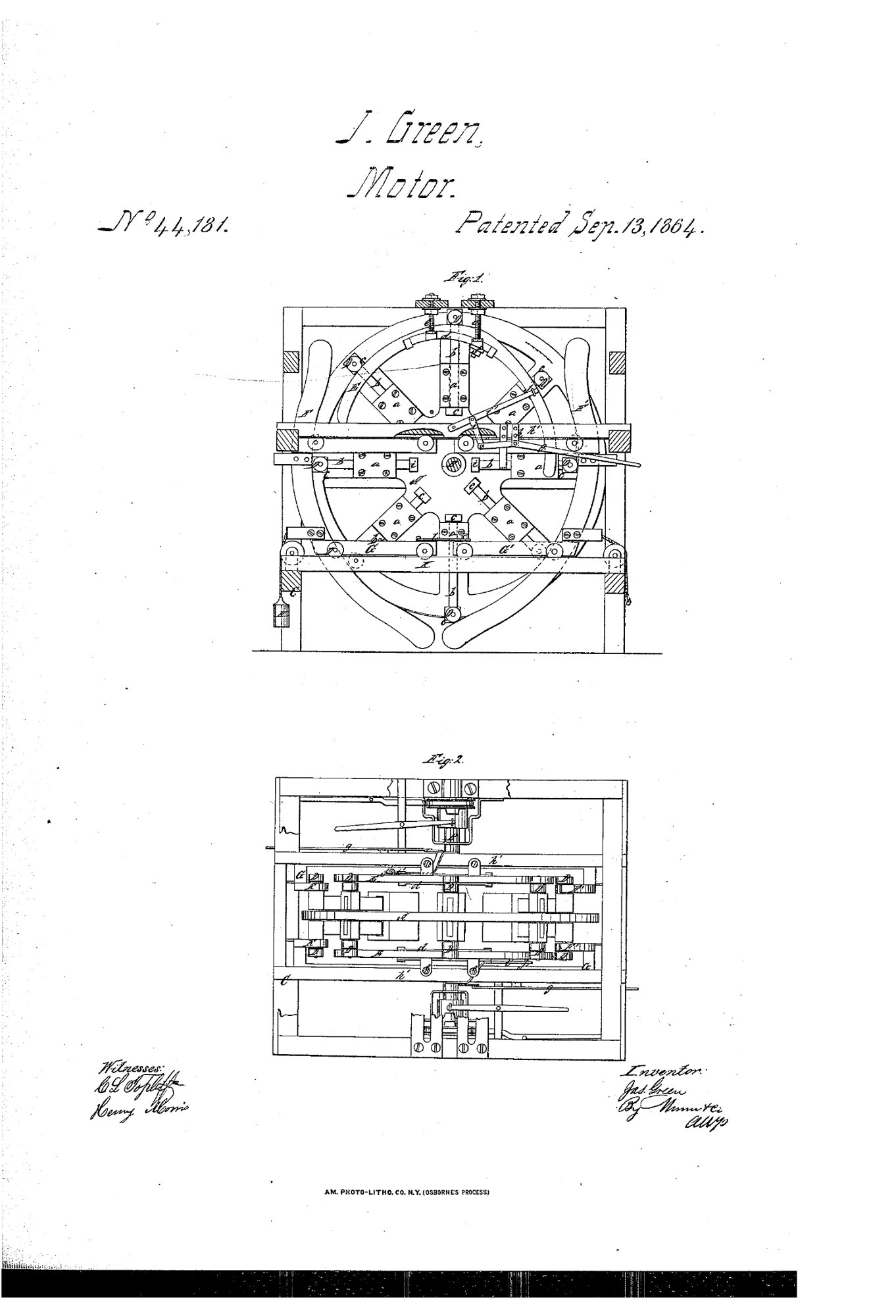
On 13 September 1864 the Office granted James Greene, of Providence, Rhode Island, US Patent 44,181, "Improvement in Motive Power". Weights on rods slide in and out of radial boxes; cams fixed to the frame push them out on one side and in on the other. The weights "on one side overbalance those on the other," he wrote, "and consequently a continuous rotary motion of the wheel will be effected."
The cams, shoe d and carriages G G′ are measured from Greene's Fig. 1, and so are the weights' positions: in on the right, out on the left, as he describes. Cam E holds the weights out over the top; F and F′ hold them in at the sides. Where the drawing hides a cam (behind shoe d and its bolts, and behind carriage G′: drawn dashed), we filled in a smooth curve through the weights it does show, and the cams' thickness is ours. Eight weights of 5 kg, 1 m out at most, are our example size. The accounting is the same as Rutkove's: whatever gravity gives through the turning, the cams take back moving the weights.
Villard de Honnecourt's mallets, about 1230
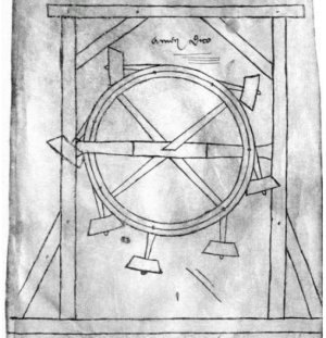
The idea is old. Villard de Honnecourt, a French builder, noted: "Many a time have skilful workmen tried to contrive a wheel that shall turn of itself; here is a way to do it by means of an uneven number of mallets, or by quicksilver." His sketch shows seven mallets hinged around the rim, the uneven number he wrote of (counted on the Bibliothèque nationale de France's full-resolution scan, MS fr. 19093, fol. 5r). Our simulation uses seven too.
Push it either way. The mallets swing out on one side and fold in on the other, and every time one hits its stop, a little of your push turns into a clack.
Simulated from Newton's laws for a wheel carrying hinged weights, 2,000 steps a second. Villard's sketch gives no sizes; these are ours.
Build your own
Change the number of mallets, how long and heavy they are, and how far they may swing out or fold in. Then push it. The chart shows the energy in the wheel: it can hold steady, or fall, but nothing you set here will ever make it climb on its own.
Every layout obeys the same rule: turn off friction, and the energy you pushed in stays in the wheel, moving between speed and height; each clack of a mallet against its stop takes a little away. We ran forty random layouts through the same simulation; none gained energy.
Redheffer's machine, 1813
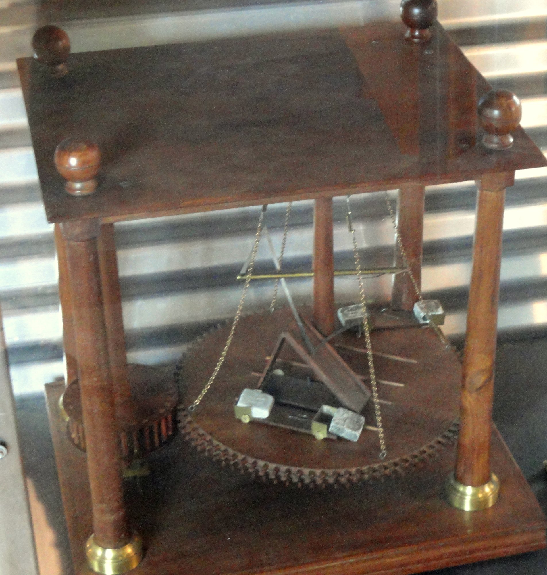

In New York in 1813, crowds were paying a dollar each to see a perpetual motion. Robert Fulton, the steamboat builder, took some persuading to go, and within minutes of walking in he said: "why, this is a crank motion." He could hear it: a wheel turned by a hand on a crank speeds up and slows down once every turn.
He knocked away some thin strips of wood that seemed to be steadying the frame, and found a catgut string running through the wall and upstairs. At the end of it, in a back loft, sat "a poor old wretch with an immense beard", gnawing a crust, "with one hand turning a crank".
The machine follows Robert Patterson's description of Redheffer's Philadelphia machine, sent to Thomas Jefferson in 1812: a wheel about five feet across, two inclined planes carrying weighted carriages, about 40 turns a minute. Colden's account of the New York machine gives no drawing, so the frame, the catgut's route and the loft are our guess, and the man is an AI-generated illustration of Colden's words. The rise and fall of the speed is our illustration of what Fulton heard.
Bessler's wheel, 1717
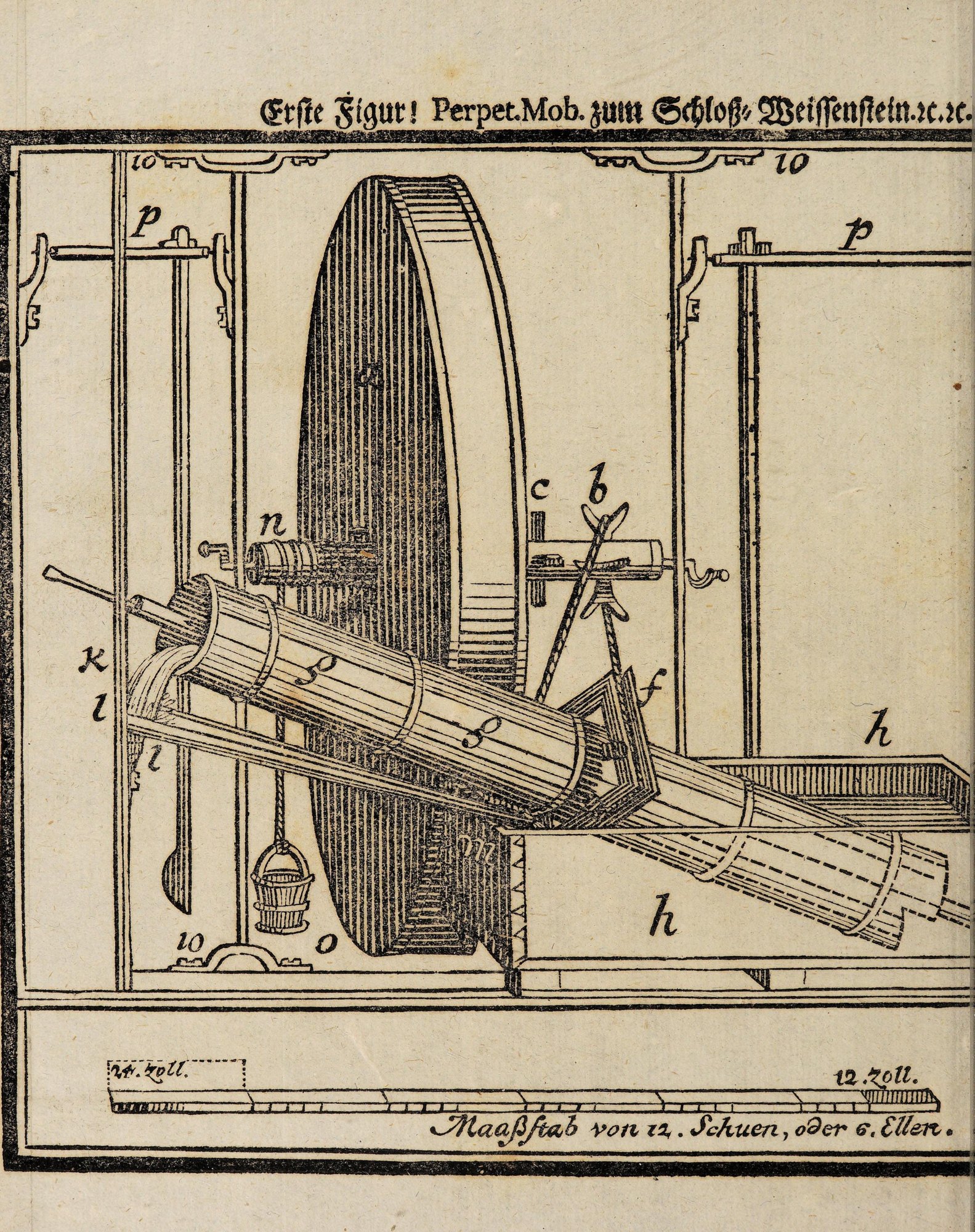
At Weissenstein Castle, Johann Bessler's wheel was sealed in a room on the twelfth of November 1717 and found still turning on the fourth of January. The Dutch professor Willem 's Gravesande described its outside to Isaac Newton in 1721: a drum twelve feet across and fourteen inches thick, of light boards covered in waxed cloth, turning 25 or 26 times a minute. After his inspection Bessler broke the wheel to pieces.
Nobody ever showed what was inside it, so the question was never settled, either way.
The drum's size, cloth and speed are 's Gravesande's; the rooms, the stands and the axle height are ours.
Keely's motor, 1872 to 1898
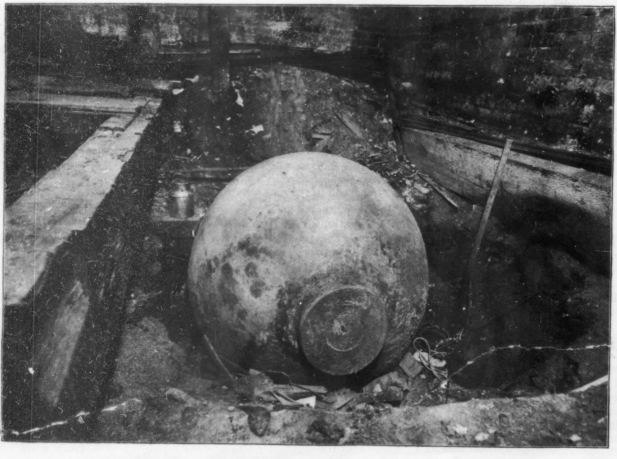
John Keely, of Philadelphia, raised money for a quarter of a century on a motor he said ran on "etheric" force. After he died, engineers took up his laboratory floors and found "a steel sphere forty inches in diameter, weighing 6,625 pounds", in a pit under a trap door, with small tubes running through the walls. Scientific American's verdict: "this most colossal humbug of the century depended for its success upon that ever-useful theme of the bogus company promoter — compressed air."
The sphere, the pit, the trap door, the tubes and the false ceiling are from Scientific American's plans of 28 January and 4 February 1899. The air gauge has no numbers because none were recorded.
Newman's machine, 1986
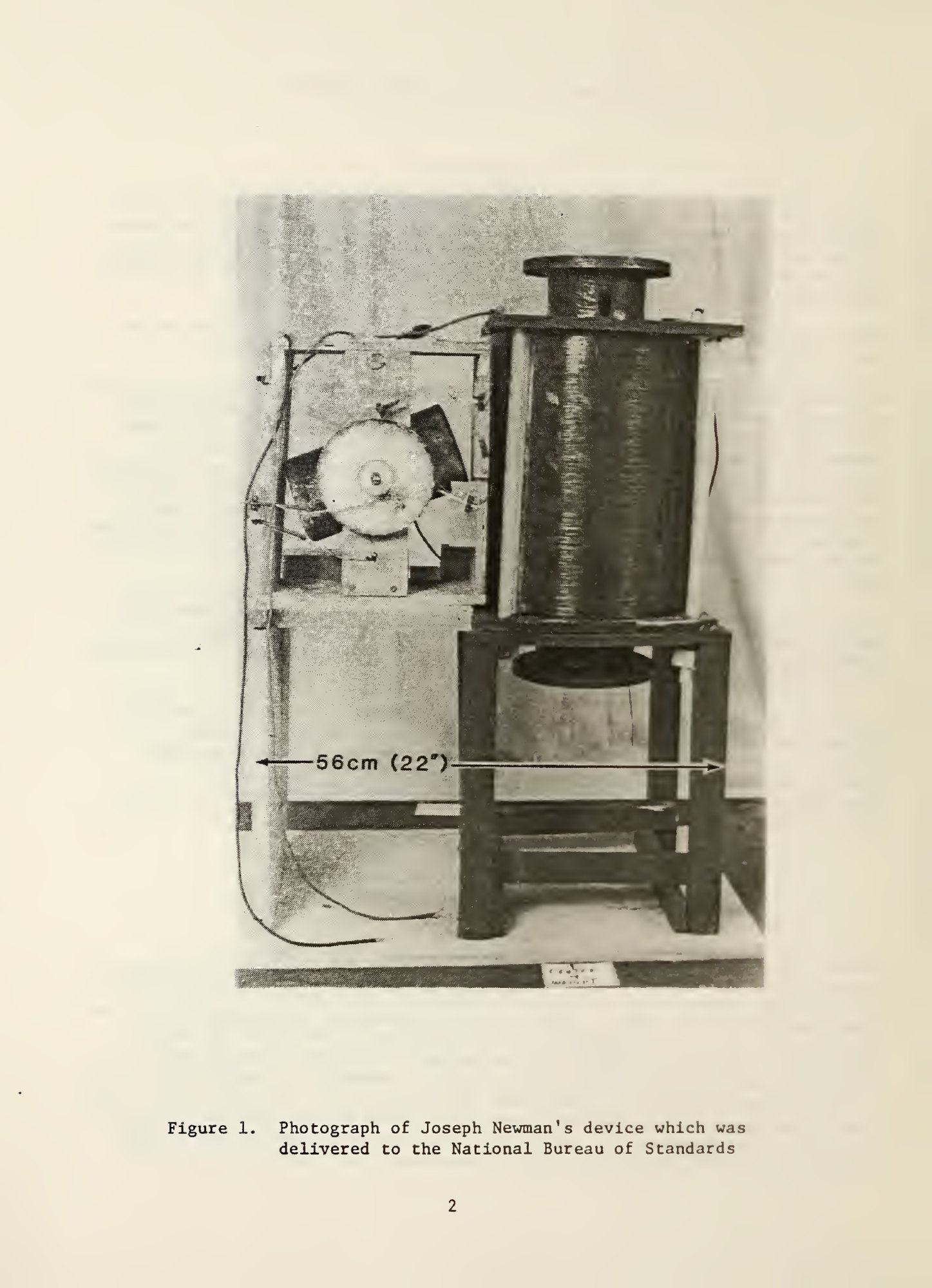
In 1980 Joseph Newman applied for a patent on an "Energy Generation System Having Higher Energy Output Than Input". In 1986 the National Bureau of Standards tested it, run on Newman's own pack of 116 nine-volt batteries. It gave back between 27 and 77 per cent of the power it took in: "At all conditions tested, the input power exceeded the output power."
The slider moves across the range the Bureau measured, which depended on the voltage, the load and the wear of the commutator; it is not any one test. How fast the batteries run down here is our illustration.
Sources
Every fact on this page comes from these, as in the episode.
Patents
- E. Rutkove, Gravity Wheel Apparatus, US Patent 3,625,089, 7 December 1971 (Google Patents).
- J. Greene, Improvement in Motive Power, US Patent 44,181, 13 September 1864 (Google Patents).
- J. W. Newman, application for "Energy Generation System Having Higher Energy Output Than Input" (1980), as reproduced in Newman v. Quigg, 681 F. Supp. 16 (D.D.C. 1988).
The machines' history
- C. D. Colden, The Life of Robert Fulton (1817), pp. 216–220 (Redheffer's machine in New York).
- R. Patterson to T. Jefferson, 30 November 1812, and the drawing he enclosed (Library of Congress; Massachusetts Historical Society).
- H. Morton, "The Redheffer Perpetual Motion", Journal of the Franklin Institute, April 1895 (Lukens's model).
- W. J. 's Gravesande to I. Newton, 1721, in H. Dircks, Perpetuum Mobile (1861); J. N. S. Allamand, ed., Oeuvres of 's Gravesande (1774), including the letter of Crousaz, 3 February 1729.
- Encyclopaedia Britannica, 11th ed. (1911), "Perpetual Motion", vol. 21, pp. 180–182 (Villard de Honnecourt).
- Villard de Honnecourt, sketchbook, Bibliothèque nationale de France, MS fr. 19093, fol. 5r (Gallica): the seven mallets are counted on this scan.
- Scientific American, 28 January and 4 February 1899, on Keely's laboratory; Leslie's Weekly, 28 November 1895.
- National Bureau of Standards, NBSIR 86-3405, Report of Tests on Joseph Newman's Device (June 1986).
- The typed transcriptions shown under the handwritten letters (Patterson to Jefferson, 30 November 1812 and 12 January 1813; Jefferson to Patterson, 27 December 1812): Founders Online, from The Papers of Thomas Jefferson, Retirement Series, vol. 5 (2008).
- Dollar amounts in today's money: the ratio of annual-average consumer prices, from the Federal Reserve Bank of Minneapolis, "Consumer Price Index, 1800-", with 2025 as today, rounded to two figures.
Images
- Patent drawings: USPTO, public domain. Villard's sketch: Bibliothèque nationale de France, MS fr. 19093, via Wikimedia Commons (public domain). Bessler's woodcut (1719): Wellcome Collection, public domain. Lukens's model: Cassier's Magazine (New York, 1895), public domain. Lukens's model today: photograph by Daderot, 2011, Wikimedia Commons, released into the public domain by the photographer. Keely's sphere: Scientific American (1899), public domain. Newman's device: NBSIR 86-3405, a US government work.
- The man in Redheffer's loft and Bessler's servant are illustrations made for the episode with an AI image generator (OpenAI, 2026). They are labelled where they appear and are not records of either person.
